
Method, system and apparatus for transmitting interleaved data between stations

Inactive Publication Date: 2008-03-11
WI LAN INC
View PDF7 Cites 6 Cited by
  • Summary
  • Abstract
  • Description
  • Claims
  • Application Information

AI Technical Summary

Benefits of technology

[0009]It is an object of the present invention to provide a novel method, system and apparatus for transmitting data between stations, which obviates or mitigates at least some of the disadvantages of the prior art.
[0020]According to yet another aspect of the present invention, there is provided a method for reducing the peak to average ratio of the energy required to transmit sets of code symbols from a transmitter to at least two receivers, the sets of code symbols being transmitted to each of said two receivers in a synchronous manner, comprising the steps of:
[0028]The present invention provides a system and method for ensuring that data transmitted between stations does not include well-aligned code symbols after interleaving. In particular, DTX or other zero energy symbols are mis-aligned in the transmission of channels to reduce peak to average transmission energy requirements and / or to reduce interference between channels experienced at a receiver. Each station employs an interleaver which is operable to mis-align data in sets of symbols to be transmitted, the interleavers employing a different set of interleaving parameters to provide the mis-alignment.

Problems solved by technology

A burst error could result in reception of ‘aaa****cc’, where ‘*’ represents the symbols obscured by a noise burst and, as will be apparent, symbol ‘b’ has been irretrievably lost.
While generally an increase in the depth of interleaving results in an improved resistance to burst errors, the amount of interleaving depth that can be employed in a system is often limited by the amount of delay, or latency, that the interleaving will cause.
With voice transmissions, latency over a certain length (typically 100 ms) will become audible to the listener, and would likely be considered unacceptable.
While such interleaving operations can provide significant benefits, the present inventors have also determined that, under some circumstances, conventional interleaving operations and methods and result in problems and / or disadvantages.

Method used


Image

  • Method, system and apparatus for transmitting interleaved data between stations
  • Method, system and apparatus for transmitting interleaved data between stations
  • Method, system and apparatus for transmitting interleaved data between stations

Examples


Embodiment Construction

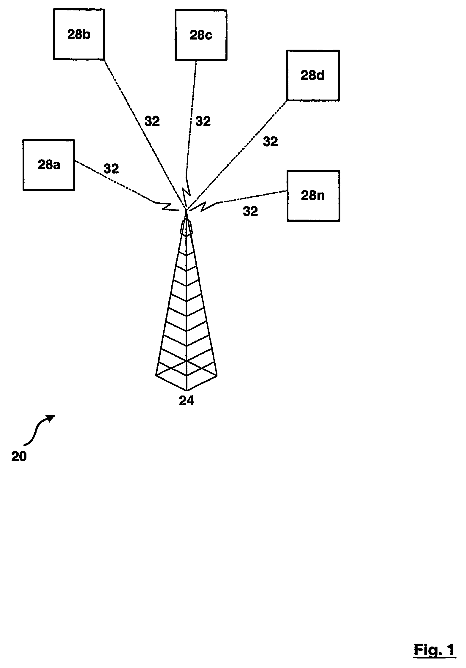
[0041]Referring now to FIG. 1, a wireless telecommunication system for transmitting data is indicated generally at 20. System 20 includes at least radio base station 24, and a plurality of subscriber stations 28a, 28b . . . 28n. The number ‘n’ of subscriber stations serviced by a base station 24 can vary depending upon the amount of radio bandwidth available and / or the configuration and requirements of the subscriber stations 28.

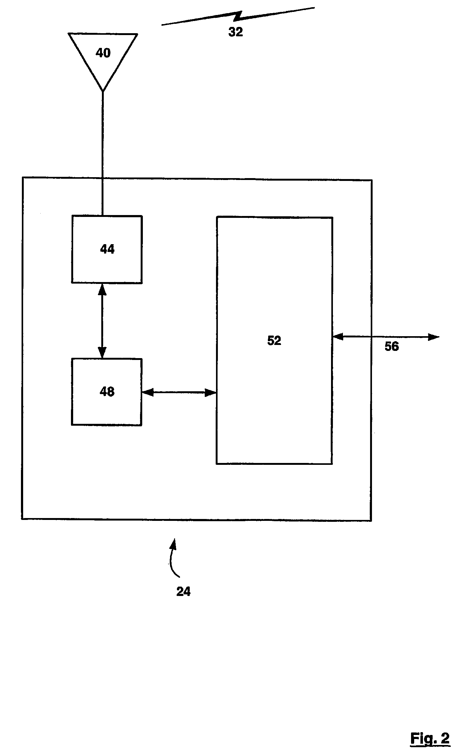
[0042]In a presently preferred embodiment, radio base station 24 is connected to at least one telecommunications network (not shown), such as a land line-based switched data network, a public switched telephone network, etc. by an appropriate gateway and one or more backhauls (also not shown). These backhaul connections can be links such as T1, T3, E1, E3, OC3 or other suitable land line link, or can be a satellite or other radio or microwave channel link or any other link suitable for operation as a backhaul as will occur to those of skill in the art.

[0043]...


PUM


Abstract

A system for transmitting data between stations, such as base stations and subscriber stations in a wireless telecommunications system, employs variable set of interleaving parameters for its interleaving operations. By using different set of interleaving parameters with the interleavers, data which would otherwise be aligned when transmitted from a station to many stations, or from many stations to a station, will not be aligned after interleaving has been performed. This reduces the peak to average ratio required for a transmitter and / or can reduce interference experienced at receivers in the system. This is especially true if a significant proportion of the otherwise aligned signals are symbols which require zero energy to transmit.

Description

FIELD OF THE INVENTION[0001]The present invention relates generally to a method and system for transmitting interleaved data between stations. More specifically, the present invention relates to a method, system and apparatus for varying the interleaving patterns between different transmissions of information signals representing data. Each transmission, whether different channels from the same transmitter at one station or different channels sent by transmitters at different stations, uses a different interleaving pattern for the signals on the channels, which are intended to be received at a receiver at a station.BACKGROUND OF THE INVENTION[0002]Communications systems use numerous techniques to improve reception quality and data rates, to manage the probability of an error being experienced at a receiver and to make efficient use of available, and limited, bandwidth. One common technique used is to interleave the information signals, referred to herein as “code symbols”, before tr...

Claims


Application Information

Patent Timeline
IPC IPC(8): H03M13/00H03C7/02H04B7/216H03M13/27H04B1/707H04J11/00H04J13/00H04L1/00
CPCH04L1/0071H04L1/0083H04B2201/70706
Inventor MANTHA, RAMESHCASTURA, JEFFREY P.VAN HEESWYK, FRANK M.
Owner WI LAN INC
Features
  • Generate Ideas
  • Intellectual Property
  • Life Sciences
  • Materials
  • Tech Scout
  • Unparalleled Data Quality
  • Higher Quality Content
  • 60% Fewer Hallucinations
Learn More