Method used for bleeding a hydraulic vehicle brake system

a brake system and hydraulic technology, applied in the direction of brake systems, braking components, transportation and packaging, etc., can solve the problems of gas dissolved in the brake fluid, unavoidable diffusion of reservoir gas through the diaphragm into the brake fluid, and unwanted compressibility of the brake fluid, so as to achieve reliable degassing of each part and easy detection

Inactive Publication Date: 2008-03-18
ROBERT BOSCH GMBH
View PDF13 Cites 9 Cited by
  • Summary
  • Abstract
  • Description
  • Claims
  • Application Information

AI Technical Summary

Problems solved by technology

In external-force service brake systems that have a hydraulic pump and a hydraulic reservoir as their external energy source, the possibility exists that gas bubbles will occur in the brake fluid, causing an unwanted compressibility of the brake fluid.
For instance, if the hydraulic reservoir is embodied as a gas pressure reservoir with a diaphragm that divides a reservoir gas from the brake fluid, then diffusion of reservoir gas through the diaphragm into the brake fluid is unavoidable.
The pressure drop need not at all be caused by a defect of the vehicle brake system; even typical pressure fluctuations in the hydraulic fluid of the vehicle brake system during operation can cause gas dissolved in the brake fluid to bubble out.

Method used


Image

  • Method used for bleeding a hydraulic vehicle brake system
  • Method used for bleeding a hydraulic vehicle brake system
  • Method used for bleeding a hydraulic vehicle brake system

Examples


Embodiment Construction

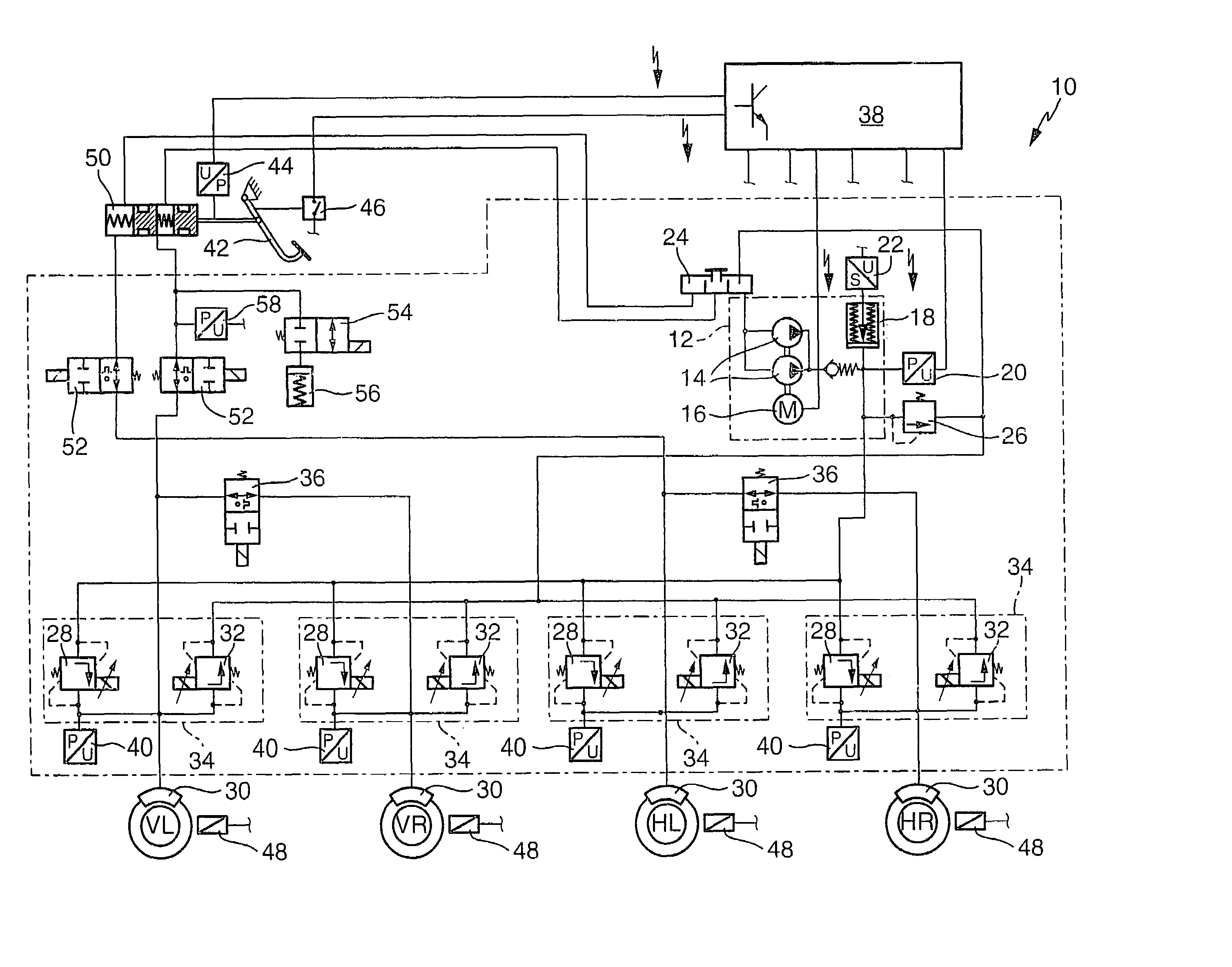
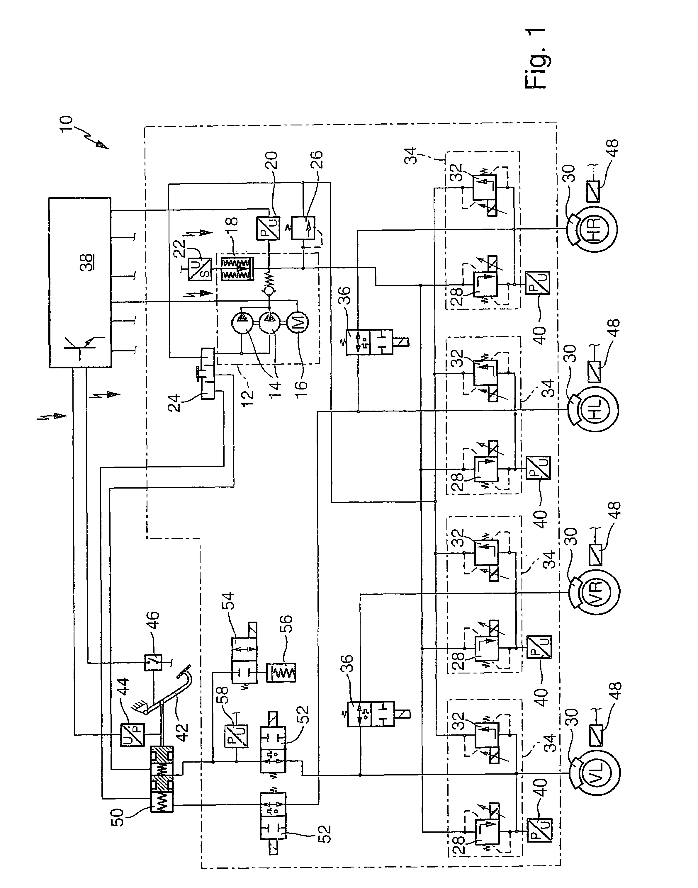
[0018]The hydraulic vehicle brake system 10 according to the invention, shown in FIG. 1, has an external-force service brake system and a muscle-powered auxiliary brake system; it is accordingly a so-called electrohydraulic vehicle brake system with a muscle-powered auxiliary brake system.

[0019]As its external energy source 12, the vehicle brake system 10 has two hydraulic pumps 14, connected hydraulically parallel, which can be driven by a common electric motor 16. A high-pressure hydraulic reservoir 18, which is a component of the external energy source 12, is connected to a pressure side of the hydraulic pumps 14. By way of example, the hydraulic reservoir 18 can be embodied as a gas pressure reservoir that has a diaphragm, as a metal bellows reservoir acted upon by gas pressure or by spring force, or as a piston reservoir acted upon by spring force. A pressure sensor 20 and a travel sensor 22 are connected to the hydraulic reservoir 18. An intake side of the hydraulic pumps 14 i...


PUM


Abstract

The invention relates to a method for degassing a hydraulic vehicle brake system that has an external-force service brake system and a muscle-powered auxiliary brake system. For the degassing, brake pressure buildup valves are opened, preferably successively, so that brake fluid flows through the brake pressure buildup valves, disconnection valves and a master cylinder and reaches a brake fluid reservoir. The brake fluid positively displaces any brake fluid containing gas from the vehicle brake system into the brake fluid reservoir, where gas bubbles can escape from the brake fluid. Compressibility of the brake fluid from gas bubbles is avoided.

Description

CROSS-REFERENCE TO RELATED APPLICATIONS[0001]This application is a 35 USC 371 application of PCT / DE 02 / 02502 filed on Jul. 9, 2002.BACKGROUND OF THE INVENTION[0002]1. Field of the Invention[0003]The invention relates to an improved method for degassing a hydraulic vehicle brake system of the type an external-force service brake system and a muscle-powered auxiliary brake system.[0004]2. Description of the Prior Art[0005]One vehicle brake system of the type with which this invention is concerned is known from International Patent Disclosure WO 98 / 28174. The external-force service brake system of the known vehicle brake system has a hydraulic pump, which can be driven by an electric motor and whose intake side is connected to a brake fluid reservoir. A hydraulic reservoir is connected to a pressure side of the hydraulic pump. The electric motor, hydraulic pump and hydraulic reservoir form an external energy source for actuating the external-force service brake system. Wheel brake cyli...

Claims


Application Information

Patent Timeline
Patent Type & Authority Patents(United States)
IPC IPC(8): B60T8/32B60T13/14B60T8/34B60T8/40B60T11/16B60T17/00
CPCB60T8/34B60T8/4081B60T11/16
Inventor SCHMIDT, LEGAL REPRESENTATIVE, GERDASCHMIDT, GUENTHER
Owner ROBERT BOSCH GMBH
Why Eureka
Try Eureka