Ophthalmoscope

a technology of ophthalmoscope and eyepiece, which is applied in the field of ophthalmoscope, can solve the problems that the eyepiece optics are still required, and the results cannot be obtained just by using the previously described measures

Inactive Publication Date: 2008-03-18
WILD MEDTEC
View PDF6 Cites 8 Cited by
  • Summary
  • Abstract
  • Description
  • Claims
  • Application Information

AI Technical Summary

Benefits of technology

[0006]The object of the present invention is to provide a more compact design of an ophthalmoscope with an oscillating diaphragm, thus to design a scanning ophthalmoscope in such a manner that it permits, using a simple optical setup, direct as possible imaging of the fundus onto an observation means and, in addition, permits coupling further light bundles into the optical setup of the ophthalmoscope without permanently impairing the optical system.
[0009]The idea behind the present invention is based on the selective use of an optical unit which images to infinity the intermediate focal plane, in which the to-be-examined fundus is imaged outside the eye with the aid of an optical imaging unit, preferably an ophthalmoscope lens, i.e. the observation beam path is conveyed into a parallel bundle of beams which is imaged via a single additional optical unit immediately into an imaging plane in which the observation means is located. This direct guidance of the observation beam path onto the observation means rules out any loss of light that would ensue using additional intermediate imaging optics including the related aberrations. This direct imaging of the observation beam onto the observation means, which is designed for example as a CCD sensor in a video camera, permits keeping the optical design of the ophthalmoscope quite small and using the ophthalmoscope itself as a handheld device or as an auxiliary module, for example, for a slit lamp.
[0010]With the aid of an optimally designed imaging optic, the entire light that is reflected for examination at the fundus can be imaged completely practically without any loss onto the corresponding detector area of the observation means via the imaging optic assigned to the observation path, thereby reducing the glare on the patient's eye considerably. The invented ophthalmoscope arrangement is especially suited as an observation means in the form of a video scanning ophthalmoscope in conjunction with a video camera.
[0013]In the parallel running beam section of both the observation beam path and the illumination beam path, which are spaced a minimal lateral distance from each other and are, in addition, disposed symmetrically to the optical axis of the optical unit, which images both beam paths into the intermediate focal plane, an additional beam path, such as for example a therapeutic laser beam, can be easily coupled into the illumination and / or observation beam path without any further optical impairment of the imaging properties of the ophthalmoscope. This opens an especially interesting degree of freedom with regard to a modular optical extension of the ophthalmoscope thereby making new diagnostic and / or treatment methods on a patient's eye possible.
[0015]Located immediately before the imaging plane of the lit area and before the observation means, which for example is designed as a COD sensor, is a diaphragm slit arrangement which is mounted in a oscillating manner and provides a diaphragm slit for the observation beam as well as a diaphragm slit for the illumination beam respectively and the two diaphragm slits interrupt respectively release the corresponding beam paths in a synchronously oscillating manner. The purpose of the diaphragm slit arrangement mounted in an oscillating manner is to obtain contrast sharp and reflection-free illumination and imaging of the fundus. In order to be able to conduct different methods of examination of the fundus, diaphragm slits of different widths have to be employed. For this purpose, the diaphragm arrangement is provided with at least two pairs of diaphragm slits, which have diaphragm slit widths of different dimensions. Corresponding dimensioning of the widths of the diaphragm slits and their oscillating behavior in relation to the illumination beam path and the observation beam path permits adapting and optimizing the illumination situation individually to the respective fundus measurement task at hand.
[0018]In order to keep the dimensions of the invented ophthalmoscope as small and compact as possible, external laser beams can be coupled in most expediently in the region of the parallel beam path. By means of suited interfaces, external laser adapters can be employed detachable or as a handle if used as a handheld device. Preferably such laser adapters can be replaced quickly and simply by means of suited flange devices.

Problems solved by technology

However, satisfactory results cannot be obtained just by means of the previously described measures.
However, an eyepiece optic is still required, because additional light beams cannot be coupled into the illumination beam path and the observation beam path without considerably interfering with the overall optical system.

Method used


Image

  • Ophthalmoscope
  • Ophthalmoscope
  • Ophthalmoscope

Examples


Embodiment Construction

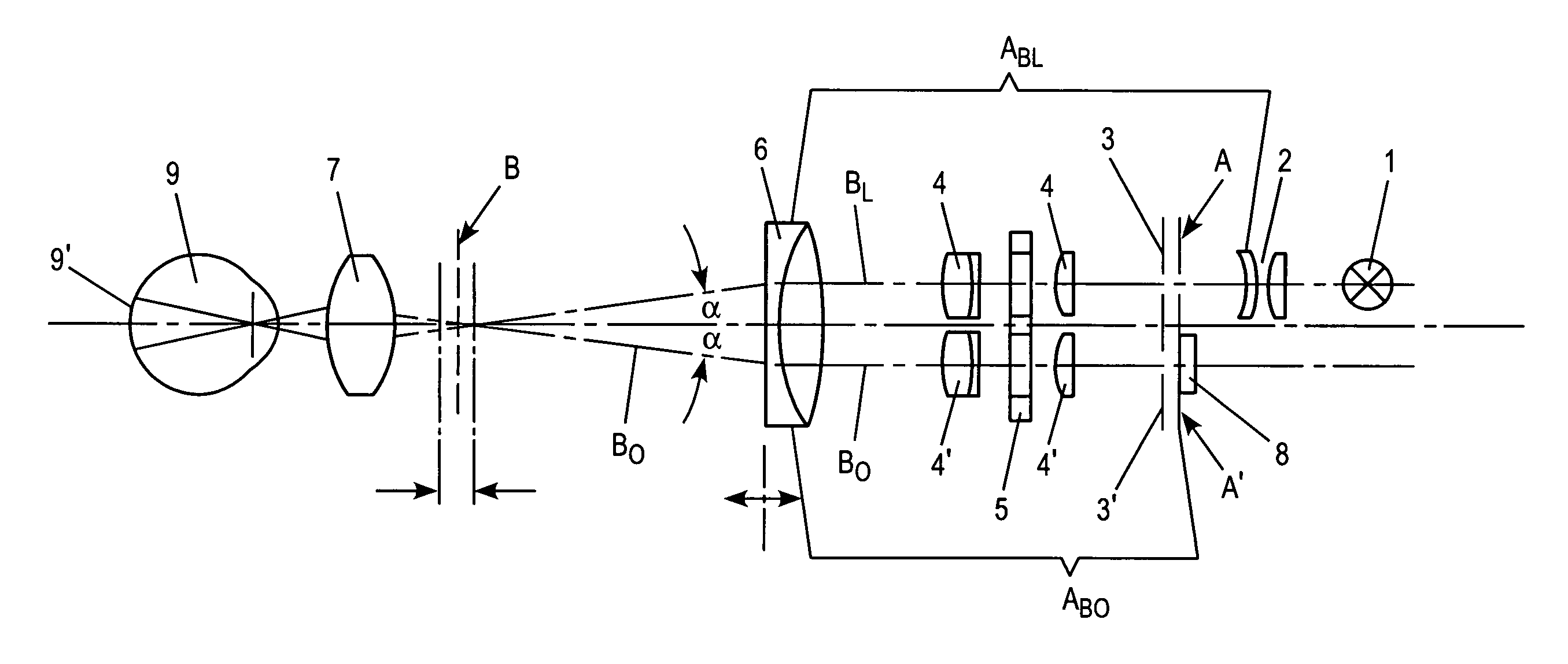
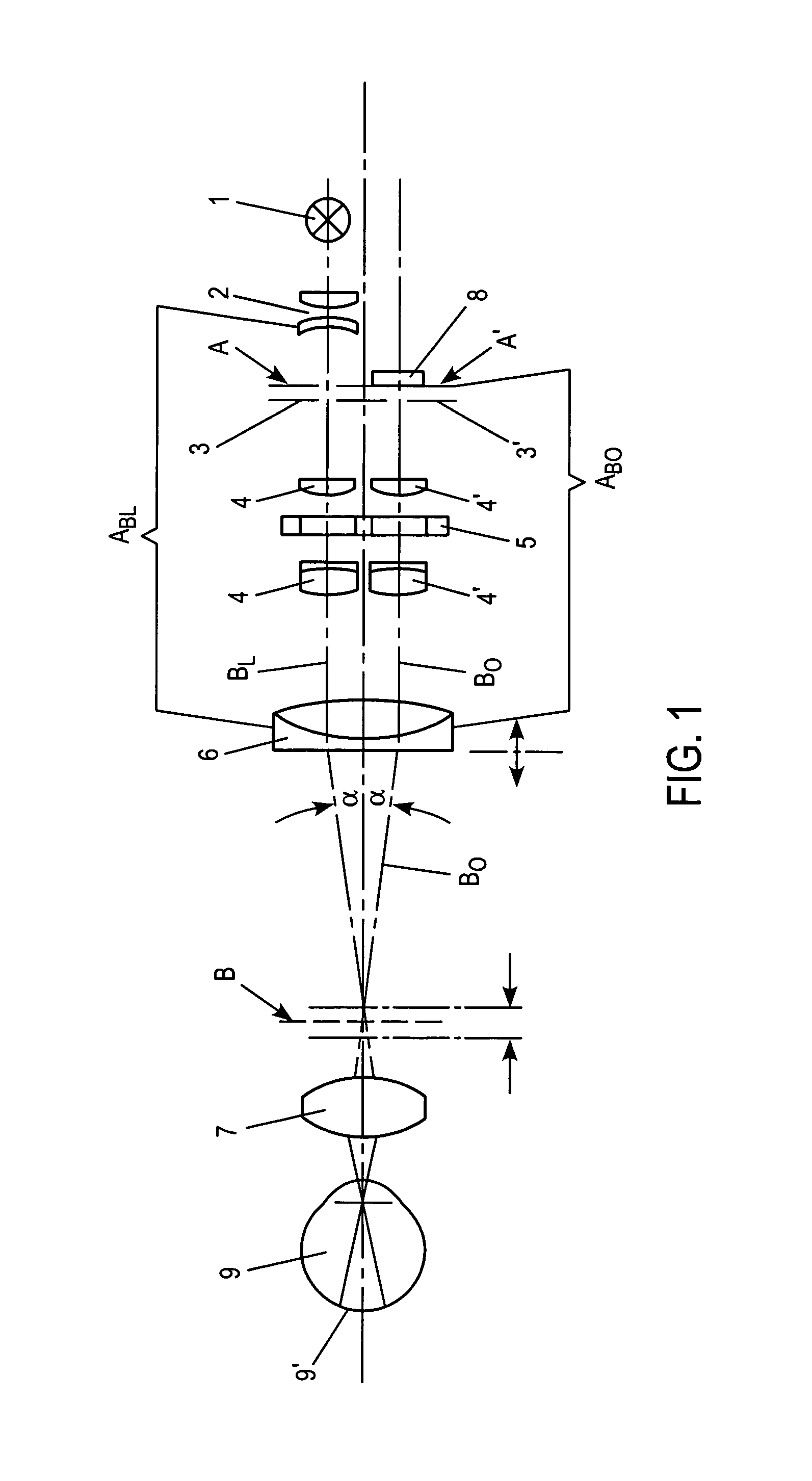
[0034]FIG. 1 shows the basic optical setup of an ophthalmoscope designed according to the present invention.

[0035]Starting from an illumination means 1, which provides a halogen lamp as a light source, follows an imaging optic ABl composed of a plurality of optical components assigned to the illumination beam Bl. The imaging optic ABl comprising a condenser optic 2, which images the light of the halogen lamp 1 in a uniformly lit area in the imaging plane A, in which a diaphragm slit arrangement 3 is provided, which is mounted in a oscillating manner in relation to the illumination beam Bl, which will be dealt with in detail later. An optic unit 4 in the form of a multi-lens objective, which conveys the illumination beam Bl in a parallel beam, is provided behind the diaphragm slit arrangement 3 in the beam direction. The parallel illumination beam bundle is focused via an optical unit 6, which is provided with at least one achromat, into an intermediate focal plane B, from which the ...


PUM


Abstract

The invention relates to an ophthalmoscope for examining the fundus of an eye of a patient, which comprises at least one illuminating device producing at least one illuminating beam, in addition to an imaging lens system which can be associated with the illuminating device and which images the illuminating beam onto the fundus of the eye of a patient; also comprising an observation device, wherein the imaging lens system images an observation beam onto the fundus of the eye, said observation beam being produced by reflecting the illuminating beam; also comprising a diaphragm arrangement introduced into the illuminating beam and the observation beam, whereby the gap of said diaphragm can be variably modified and synchronized. The invention is characterized in that the imaging lens system is formed in such a manner that an intermediate focal plane is created along the illuminating beam and the observation beam, wherein the fundus of the eye and the illuminating device are imaged, so that the intermediate focal plane is imaged infinitively, and so that the infinitively formed intermediate focal plane is imaged on an image plane of the observing beam, wherein the observation device is arranged.

Description

FIELD OF THE INVENTION[0001]The present invention relates to an ophthalmoscope for examining the fundus of a patient's eye having at least one illumination means producing at least one illumination beam as well as an imaging optic which can be assigned to the illumination means and which images the illumination beam onto the fundus of the patient's eye via an intermediate focal plane. Furthermore, the ophthalmoscope has at least one observation means as well as an imaging optics which can be assigned to the observation means and which images an observation beam generated by reflection of the illumination beam on the fundus via the intermediate focal plane into the observation means. Finally provided in the illumination beam and the observation beam is a diaphragm arrangement having at least one diaphragm slit which can be introduced in the illumination beam and the observation beam respectively, the diaphragm arrangement being mounted in such a manner that it oscillates synchronousl...

Claims


Application Information

Patent Timeline
Patent Type & Authority Patents(United States)
IPC IPC(8): A61B3/10A61B3/14A61B3/12A61B3/135A61F9/007
CPCA61B3/12A61B3/145
Inventor ZORN, WOLFGANGREIS, WERNERSPALTMANN, RONALD
Owner WILD MEDTEC
Why Eureka
Try Eureka