Turbocharger

a technology of turbocharger and axial shaft, which is applied in the direction of positive displacement liquid engine, piston pump, liquid fuel engine, etc., can solve the problems of serious accidents, relatively expensive and complicated strengthening, and the shaft is no longer fixed axially, and achieves simple operation, easy to dismantle, and easy to use.

Inactive Publication Date: 2008-03-18
ABB (SCHWEIZ) AG
View PDF7 Cites 26 Cited by
  • Summary
  • Abstract
  • Description
  • Claims
  • Application Information

AI Technical Summary

Benefits of technology

[0004]The object of the invention, in the case of a turbocharger of the type mentioned at the beginning, is to propose a simple and cost-effective device for preventing the escape of the shaft from the housing.
[0007]The advantages of the invention can be seen, inter alia, in the fact that, in the event of the compressor wheel bursting, the remaining shaft and the turbine wheel fastened thereto can be safely held in the housing with the aid of simple means. Despite the means used for the axial locking, the turbocharger can still be assembled and operated in the same known conventional manner without making assembly or dismantling more difficult. Effects on the rotor, i.e. unbalance, are prevented through the use of essentially radially symmetrical means for the axial locking.

Problems solved by technology

A disadvantage with this construction is that, in the event of the compressor wheel bursting, the shaft is no longer fixed axially in the housing and by the bearings, and the shaft may escape axially from the housing on account of the axial forces produced by the turbine wheel.
However, this strengthening is relatively expensive and complicated, and, if high axial forces produced by the turbine wheel act on the shaft, the latter can nonetheless escape from the housing and lead to serious accidents.

Method used


Image

  • Turbocharger
  • Turbocharger
  • Turbocharger

Examples


first embodiment

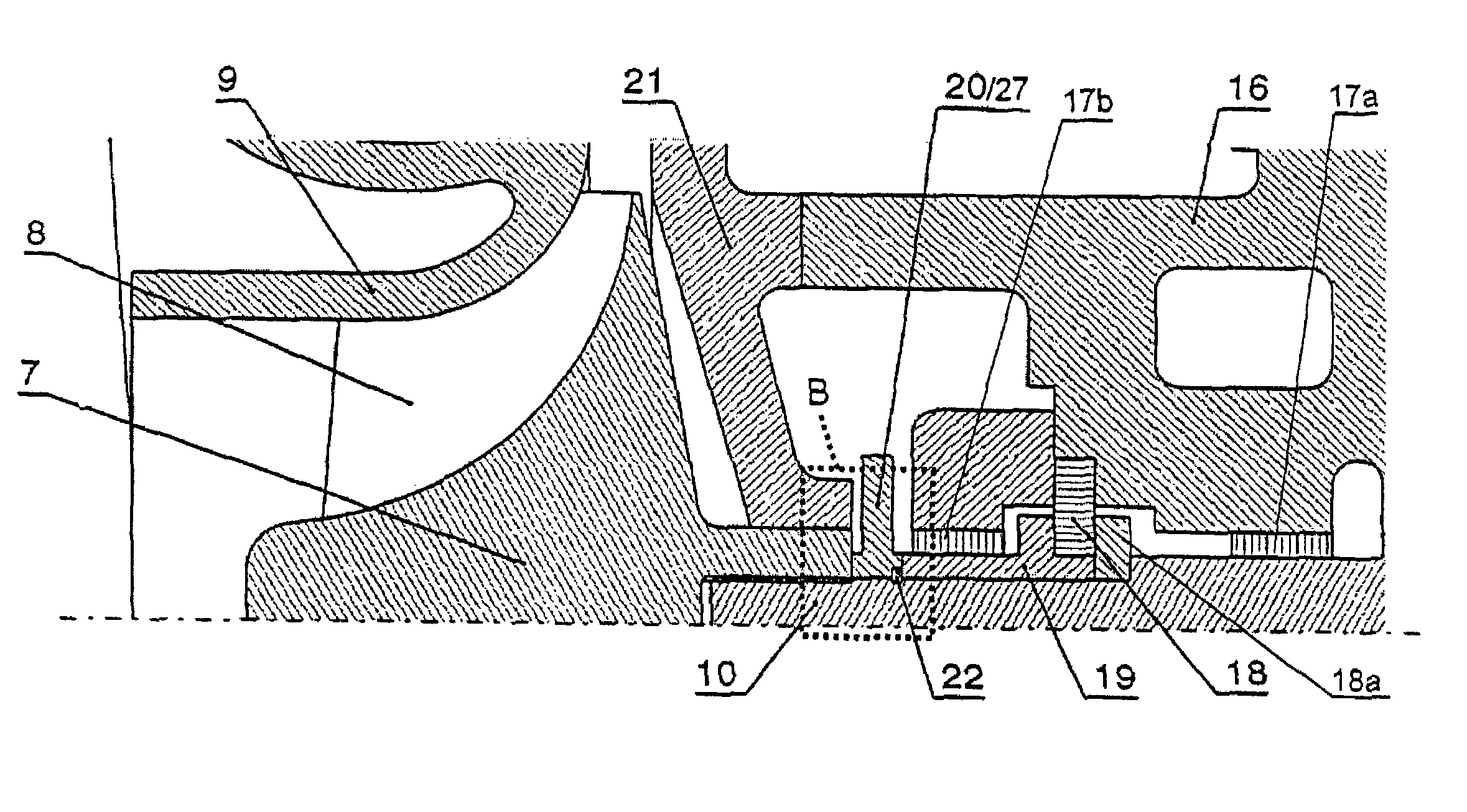
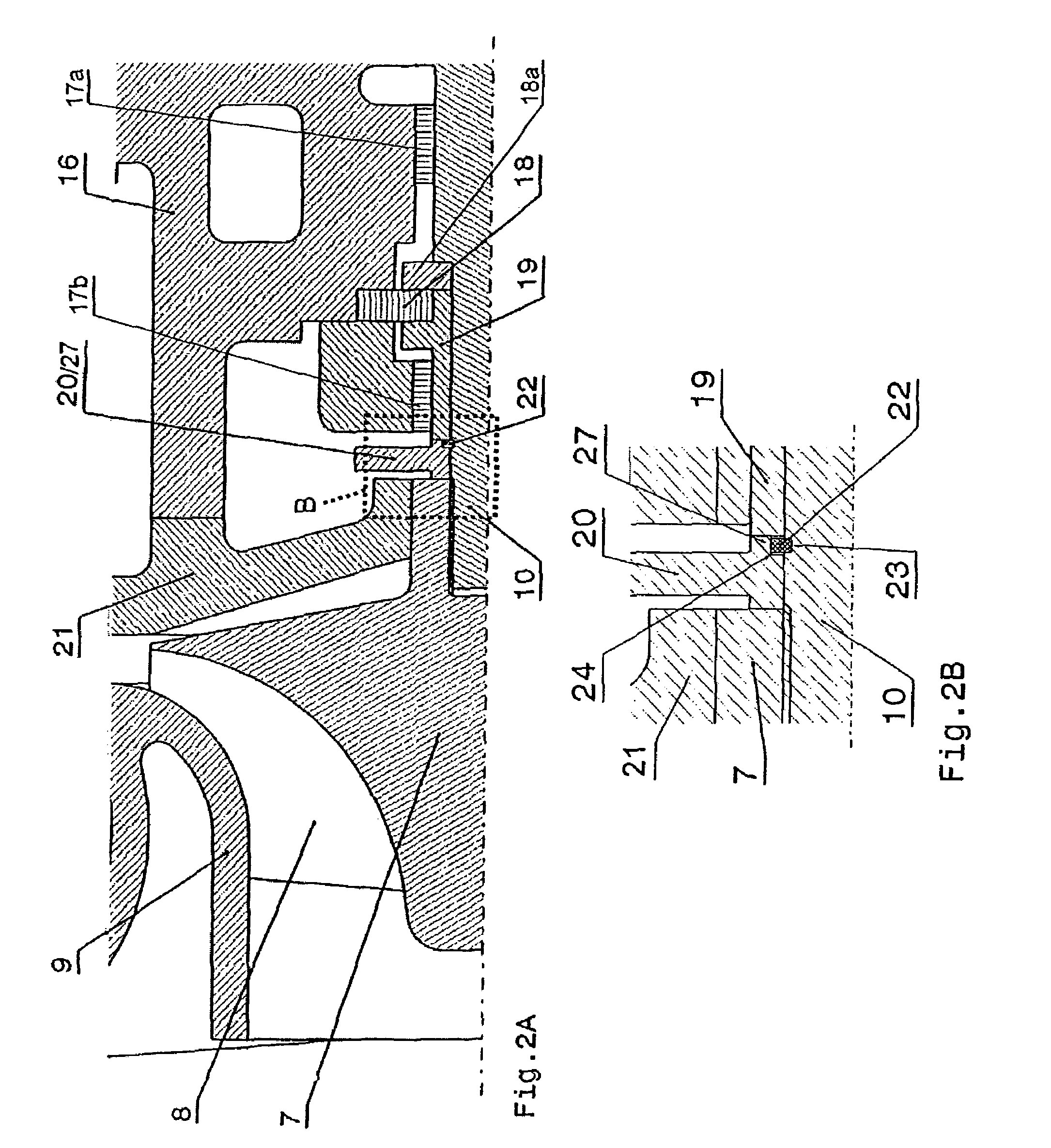
[0013]FIG. 2A shows detail A from FIG. 1 in an enlargement, but with the subject matter of the invention;

[0014]FIG. 2B shows detail B from FIG. 2A in a further enlargement of the first embodiment of the subject matter of the invention; and

second embodiment

[0015]FIG. 3 shows the subject matter of the invention in an illustration analogous to the illustration in FIG. 2A.

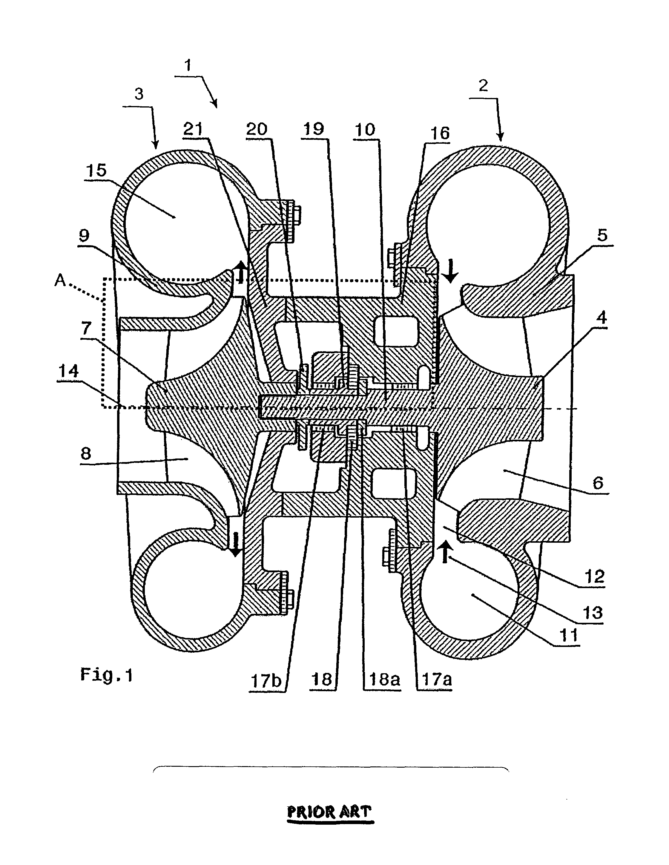
[0016]Only the elements which are essential for the direct understanding of the invention are shown. Of the system, for example, the associated internal combustion engine is not shown.

Ways of Implementing the Invention

[0017]A turbocharger 1 comprising a turbine 2 and a compressor 3 is shown schematically in longitudinal section in FIG. 1. The turbine 2 essentially comprises a turbine wheel 4 with turbine blades 6 and a turbine housing 5, which encloses the turbine wheel 4. The compressor 3 comprises a compressor wheel 7 with compressor blades 8 and a compressor housing 9 enclosing the compressor wheel 7. The turbine wheel 4 and the compressor wheel 7 are connected to one another via a shaft 10, which is mounted in the bearing housing by means of various bearing elements. In the example shown here, the turbine 2 and the compressor 3 are designed as a radial-flow turbine ...


PUM


Abstract

In a turbocharger (1), comprising a turbine (2) and a compressor (3) connected to the turbine (2), the turbine (2) contains a turbine wheel (4) and the compressor (3) contains a compressor wheel (7) which are connected to one another by means of a shaft (10) and are arranged in a housing (5, 9, 16). During operation, if the compressor wheel (7) separates from the shaft (10), an axial force acts on the turbine wheel (4) and the shaft (10) connected thereto.A means (22, 25) for axially locking the shaft and the turbine wheel connected thereto in the housing (5, 9, 16) is arranged on the shaft (10) connected to the turbine wheel (4).

Description

TECHNICAL FIELD[0001]The invention is based on a turbocharger according to the preamble of the first claim.PRIOR ART[0002]By means of turbochargers, the exhaust gases of an internal combustion engine can be used for compressing the combustion air fed to the internal combustion engine. To this end, the turbocharger has a turbine and a compressor which sit on a common shaft. The exhaust gases of the internal combustion engine are expanded in the turbine and converted into rotational energy. The rotational energy obtained is transmitted by means of the shaft to the compressor, which compresses the air fed to the internal combustion engine. By using the energy of the exhaust gases for compressing the air fed to the combustion process of the internal combustion engine, the combustion process and the energy efficiency of the internal combustion engine can be optimized.[0003]Since the center part of the housing in turbochargers, on account of the bearing contained therein, is normally pref...

Claims


Application Information

Patent Timeline
Patent Type & Authority Patents(United States)
IPC IPC(8): F04B17/00F01D5/04F01D1/00F01D21/04F02B39/00F02B39/16F02C6/12
CPCF01D21/045F02C6/12F04D29/266F05D2220/40F01D21/04
Inventor KOPP, ADRIANGARTMANN, MARCOGWEHENBERGER, TOBIAS
Owner ABB (SCHWEIZ) AG
Why Eureka
Try Eureka