Efficient power amplification system

a power amplifier and efficient technology, applied in the direction of gated amplifiers, amplifiers with semiconductor devices only, amplifiers with semiconductor devices, etc., can solve the problem of increasing the size and power requirements of transmitters, difficult to implement amplifiers in monolithic integrated circuit designs, and power amplifiers with optimal impedance matching in one frequency band may not be optimized for operation in a different frequency band. problem, to achieve the effect of efficient power amplification of electromagnetic signals

Inactive Publication Date: 2008-03-18
NORTH SOUTH HLDG
View PDF50 Cites 83 Cited by
  • Summary
  • Abstract
  • Description
  • Claims
  • Application Information

AI Technical Summary

Problems solved by technology

Impedance may be dependant on the operating frequency and, therefore, a power amplifier having optimal impedance matching in one frequency band may not be optimized for operation in a different frequency band.
However, separate amplifying chains may require numerous switches to provide a desired combination of amplifier stages.
This may make it difficult to implement the amplifier in a monolithic integrated circuit design.
It also may increase the size and the power requirements for the transmitter.
There may be a tradeoff between efficiency and linearity, however, with improvement in one coming at the expense of the other.
As a result, being designed for the highest power level with maximum available efficiency, a power amplifier may tend to operate less efficiently at lower power levels, which may shorten the life of a battery and reduce talk time duration.
One problem with this approach, however, is poor efficiency at backoff output powers (i.e., output powers less than the maximum power).
This approach, however, requires an increase in the number of required switches and impedance networks, which may increase both the size and the power requirements of the power amplifier and the transmitter.
In addition, the problem of poor efficiency at backoff power levels remains.
These requirements may make it difficult to implement the amplifier in a monolithic integrated circuit design, which may result in increased size and cost of the entire power amplifier and transmitter.

Method used


Image

  • Efficient power amplification system
  • Efficient power amplification system
  • Efficient power amplification system

Examples


Embodiment Construction

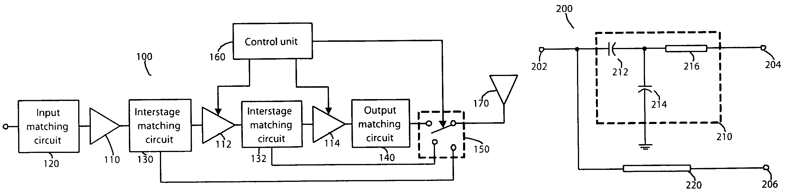
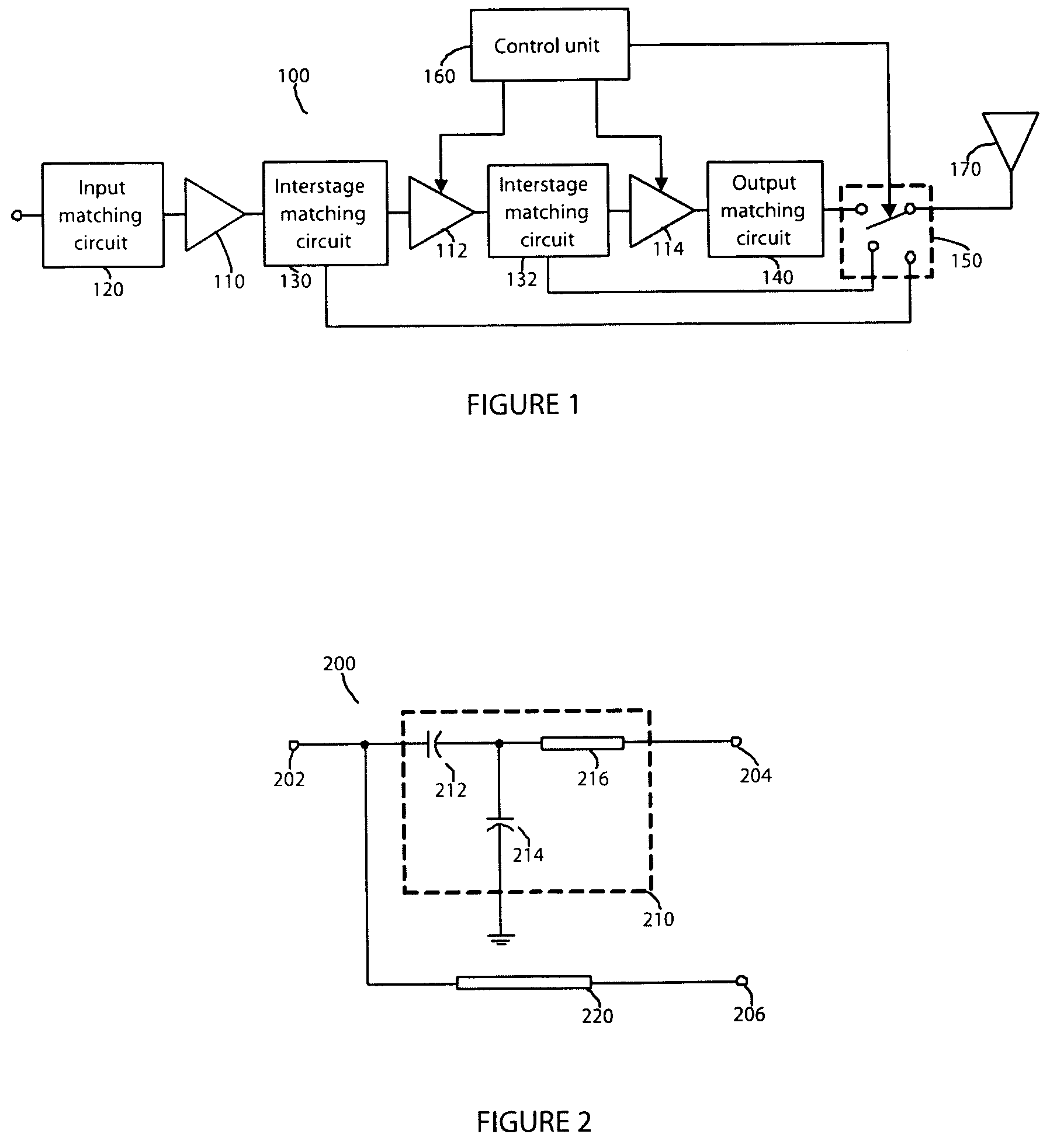
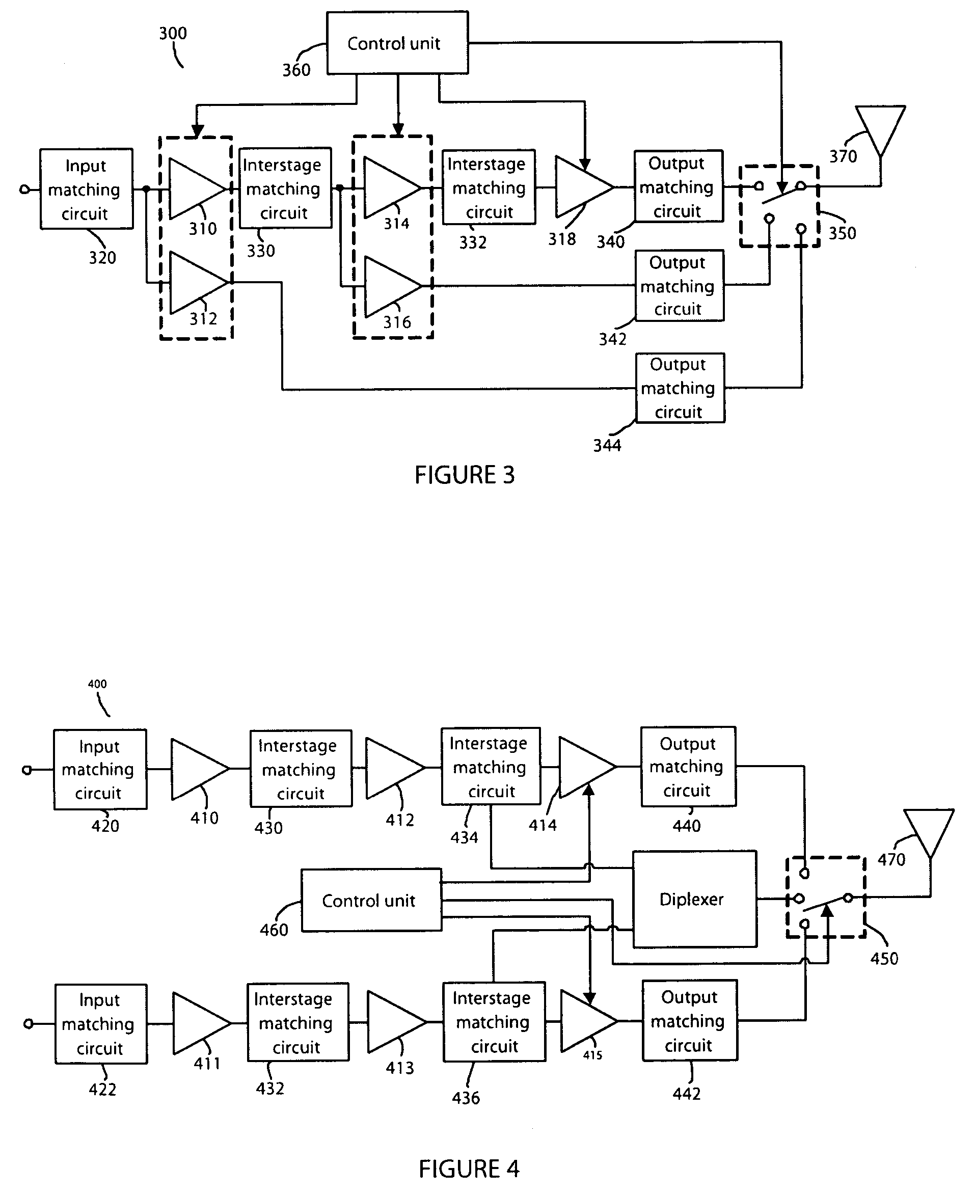
[0020]Embodiments of the invention include apparatus, methods and articles of manufacture for amplifying and transmitting electromagnetic waves and signals. For illustration purposes, an exemplary embodiment comprises a power amplifier system. The power amplification systems described in this application may be implemented in a wide range of applications, such as, for example, transmitters, transceivers, etc. For purposes of illustration, an exemplary power amplification system according to one aspect of the invention is illustrated in FIG. 1.

[0021]FIG. 1 is a block diagram illustrating a system 100 for efficient power amplification according to one aspect of the invention. The system includes three power amplifier stages 110, 112, and 114. Each of the amplifier stages may include an active device such as a transistor. For example, each of the amplifier stages may be one or more bipolar transistors.

[0022]An input matching circuit 120 is in communication with the first amplifier stag...


PUM


Abstract

A system for efficient power amplification of an electromagnetic signal includes a switchplexer having at least two inputs and an output. The switchplexer may be configured to provide communication between a selected switchplexer input and the switchplexer output. The system also may include two or more amplifier stages, each having an input and an output, and one or more output matching circuits. Each of the output matching circuits may include an input in communication with one of the amplifier stage outputs, as well as an output in communication with one of the switchplexer inputs. A control unit may be configured to control selection of the selected switchplexer input and to selectively activate at least one of the amplifier stages.

Description

FIELD OF THE INVENTION[0001]The invention relates generally to power amplifiers in wireless communication transmitters and transceivers and, more particularly, to a system and method for efficient power amplification.BACKGROUND OF THE INVENTION[0002]In modern wireless communication systems it may be desirable for a transmitter or transceiver to operate simultaneously in both an efficient and linear manner. It also may be desirable for the transmitter to operate in multiple frequency bands. Power amplifiers used in transmitters may be optimized for use in a particular mode and frequency band to maximize efficiency. Such optimization may require the amplifier to be biased in a certain manner. Additionally, impedances may need to be matched between components within the power amplifier and between the amplifier and adjacent components.[0003]For example, a transmitter may be designed to operate in two separate frequency bands, such as the GSM850 / 900 (824-915 MHz) and DCS1800 / PCS1900 (17...

Claims


Application Information

Patent Timeline
Patent Type & Authority Patents(United States)
IPC IPC(8): H03F1/14
CPCH03F1/0277H03F3/72H03F2203/7221H03F2203/7236
Inventor GREBENNIKOV, ANDREI
Owner NORTH SOUTH HLDG
Why Eureka
Try Eureka