
Refractive-diffractive hybrid lens, in particular for beam shaping of high power diode lasers

Inactive Publication Date: 2008-03-18
SCHOTT AG
View PDF21 Cites 6 Cited by
  • Summary
  • Abstract
  • Description
  • Claims
  • Application Information

AI Technical Summary

Benefits of technology

[0009]It is the object of the invention to specify a cylindrical lens that can preferably be fabricated cost effectively and precisely and in the case of which it is possible to correct aberrations owing to cylinder shape or defects in cylinder shape as well as defects in semiconductor diode laser arrangements.

Problems solved by technology

Lens arrays and prism arrays are generally difficult to fabricate and have, between the respective prisms, stepped lateral surfaces that are disadvantageous for the propagation of light by reflection.
Not only is the high outlay on production of aspheric surfaces adjusted relative to one another disadvantageous in such systems, so also is the difficult exact mounting, for example, in the exact alignment relative to a stationary light source.
However, what is disadvantageous here is that even a slight deviation in the refractive power and / or the dimensional accuracy of the lens owing to the manufacturing tolerances would also respectively require different spacings, and this could be taken into account only with great effort.

Method used


Image

  • Refractive-diffractive hybrid lens, in particular for beam shaping of high power diode lasers
  • Refractive-diffractive hybrid lens, in particular for beam shaping of high power diode lasers
  • Refractive-diffractive hybrid lens, in particular for beam shaping of high power diode lasers

Examples


Embodiment Construction

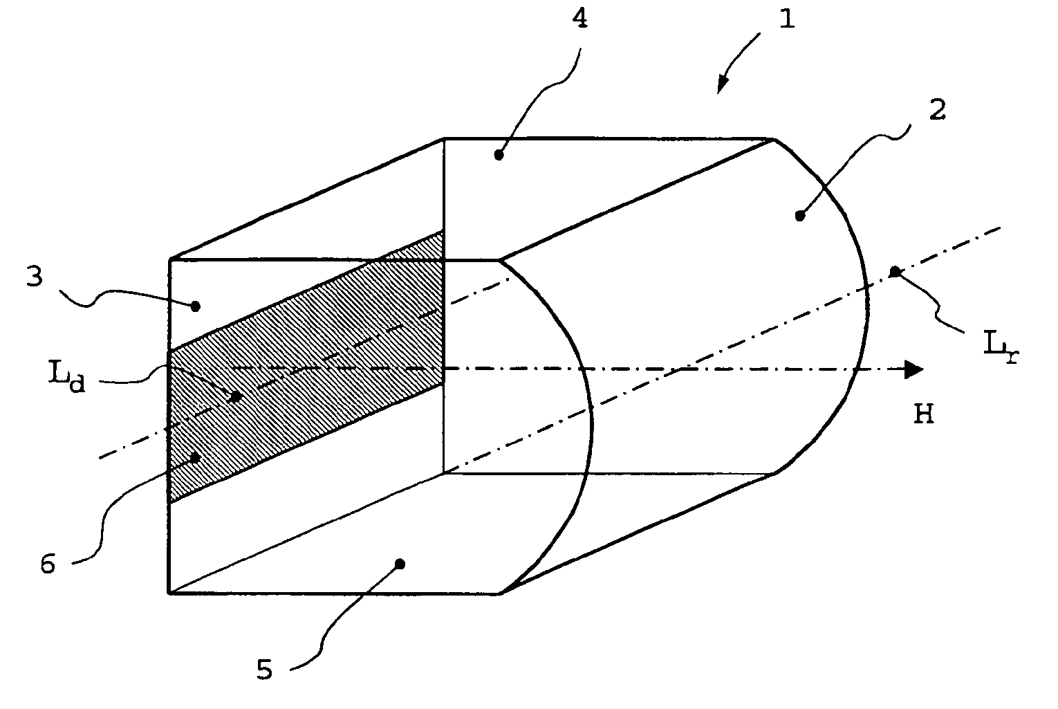
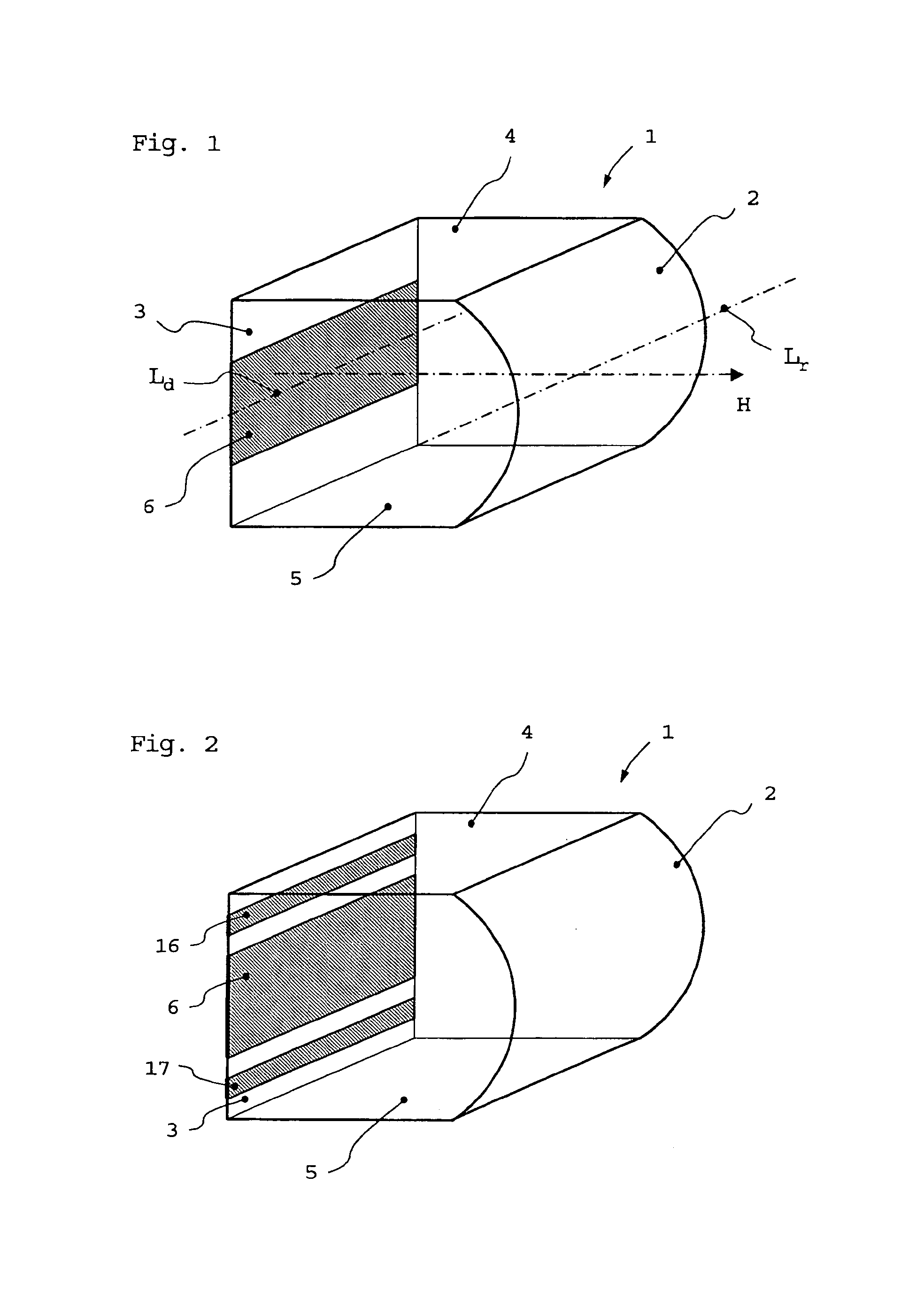
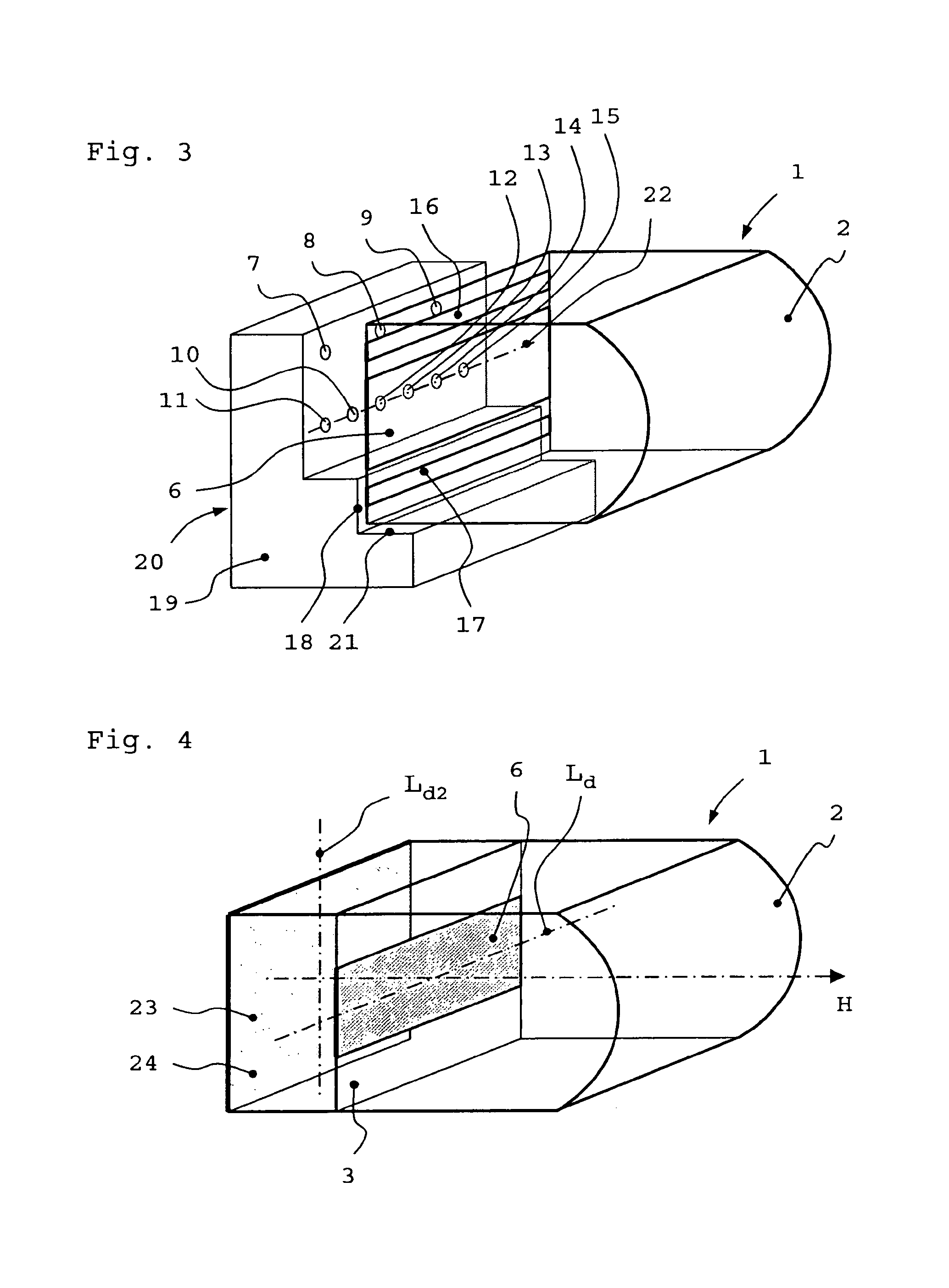
[0035]It may be firstly stated in the following detailed description of the individual embodiments preferred according to the invention that the attached drawings are merely of an explanatory nature and do not necessarily show actual embodiments in illustrations of correct scale.

[0036]It may further be pointed out that the term “optical longitudinal axis of a cylindrical lens” that is used in the present description and in the claims is not restricted to physical geometric dimensions of said lens.

[0037]In the case of conventional, purely refractive cylindrical lenses or cylindrical lens systems, this term Lr is intended to denote that axis which extends in the principal optical plane of the cylindrical lens parallel to the spatial physical longitudinal axis of this lens and cuts a principal beam path that advances essentially unbroken through the cylindrical lens and thereby cuts a focal beam that passes through the middle of the cylindrical lens.

[0038]In the case of a purely diffra...


PUM

PropertyMeasurementUnit
Elongationaaaaaaaaaa
Refractionaaaaaaaaaa

Abstract

A cylindrical lens having a refractive optical element and a diffractive optical element is provided. The cylindrical lens can be fabricated cost effectively and precisely, and optical aberrations and defects in semiconductor diode laser arrangements can be corrected. The diffractive optical element can include various segments.

Description

BACKGROUND OF THE INVENTION[0001]1. Field of the Invention[0002]The invention relates to optical lenses and lens systems in general and to cylindrical lenses and cylindrical lens systems such as are used in beam shaping of the light from high power semiconductor diode lasers and corresponding arrays.[0003]2. Description of Related Art[0004]A cylindrical lens is understood as a transparent optically refracting body having at least one bounded free surface. The real or virtual combination point of beams entering in an axially parallel fashion is understood as the focal point.[0005]Devices for beam shaping the light of high power lasers are conventionally constructed in a complicated fashion using multilens refractive systems (for example lens arrays and / or prism arrays): see, for example, DE 195 00 513 or else DE 198 46 532 and EP 0 961 152. These optical systems serve the purpose of carrying out beam shaping by largely retaining the optical quality of the laser diode emitter radiatio...

Claims


Application Information

Patent Timeline
IPC IPC(8): G02B3/06G02B13/18G02B5/18G02B1/11G02B27/09H01S5/00H01S5/40
CPCG02B5/1814G02B27/0944G02B27/0966G02B27/4272G02B19/0009G02B19/0052G02B19/0014G02B27/60H01S5/005H01S5/4025
Inventor PAWLOWSKI, EDGARBRINKMANN, MATTHIASBEIER, WOLFRAMLUTTMER, JORGWOLFING, BERNDEBELING, POLINA
Owner SCHOTT AG
Learn More