Rotary motor clipper with linear drive system

a technology of linear drive and rotary motor, which is applied in the direction of metal working apparatuses, etc., can solve the problems of increasing operational noise, reducing the operational efficiency of the clipper, and wear and deterioration of the driving end so as to reduce the accumulation of hair clippings, reduce the wear and deterioration of the drive element, and increase the operational life

Inactive Publication Date: 2008-03-25
WAHL CLIPPER
View PDF15 Cites 34 Cited by
  • Summary
  • Abstract
  • Description
  • Claims
  • Application Information

AI Technical Summary

Benefits of technology

[0007]The above-listed needs are met or exceeded by the present hair cutting device which overcomes the limitations of the current technology. Among other things, the present cutting device is designed for linear movement of the drive element, which maintains a constant engagement with the moving blade. In contrast to conventional arcuate or semi-arcuate drive systems, the present system provides “true” linear motion of the drive element throughout its stroke as generated by rotation of the motor output shaft. In this application, “true” linear motion refers to the fact that a drive tip of the drive element does not move in or out, or up or down relative to the engagement with the moving blade of the bladeset. Instead, a constant relationship is maintained between the drive element throughout the linear reciprocating stroke of the moving blade. As such, wear of the drive element is reduced and operational life is increased. Another feature of the present hair clipper is that the housing is provided with a configuration shaped for reducing the accumulation of hair clippings in the bladeset area. A spheroidal shape promotes the escape of clippings from this area, thus facilitating the movement of the clipper through a subject's hair. Still another feature of the present hair clipper is the provision of a motor actuator switch handle projecting from an underside of the housing, preferably from a recess in the underside, for promoting more positive operator control of the unit.
[0009]In another embodiment, a hair clipper includes a motor with a rotary output shaft, a bladeset including a stationary blade and a moving blade configured for reciprocation relative to the stationary blade, a drive system configured for transferring motion from the output shaft to the bladeset and a housing enclosing the motor and at least a portion of the drive system. The housing is provided with a spheroidal shape adjacent the bladeset for promoting flow of cut hair away from the bladeset.

Problems solved by technology

In time, operational conditions, including heat and friction, combine to cause wear and deterioration of the driving end of the drive element.
Such wear decreases operational efficiency of the clipper and often increases operational noise.
Another operational problem of conventional hair cutting devices is that hair clippings tend to accumulate in the area of the bladeset.
The accumulation, which is more severe when the hair is wet, impedes the efficiency of the cutting device, since the unit does not move as quickly through the subject's hair.
Still another operational problem of many conventional hair cutting devices is that the on / off switch is typically located on the top or side of the housing, where it is often accidentally actuated by the user during use.
This may interfere with the cutting operation, especially when the operator is in the midst of styling, and prefers minimum interruption.

Method used


Image

  • Rotary motor clipper with linear drive system
  • Rotary motor clipper with linear drive system
  • Rotary motor clipper with linear drive system

Examples


Embodiment Construction

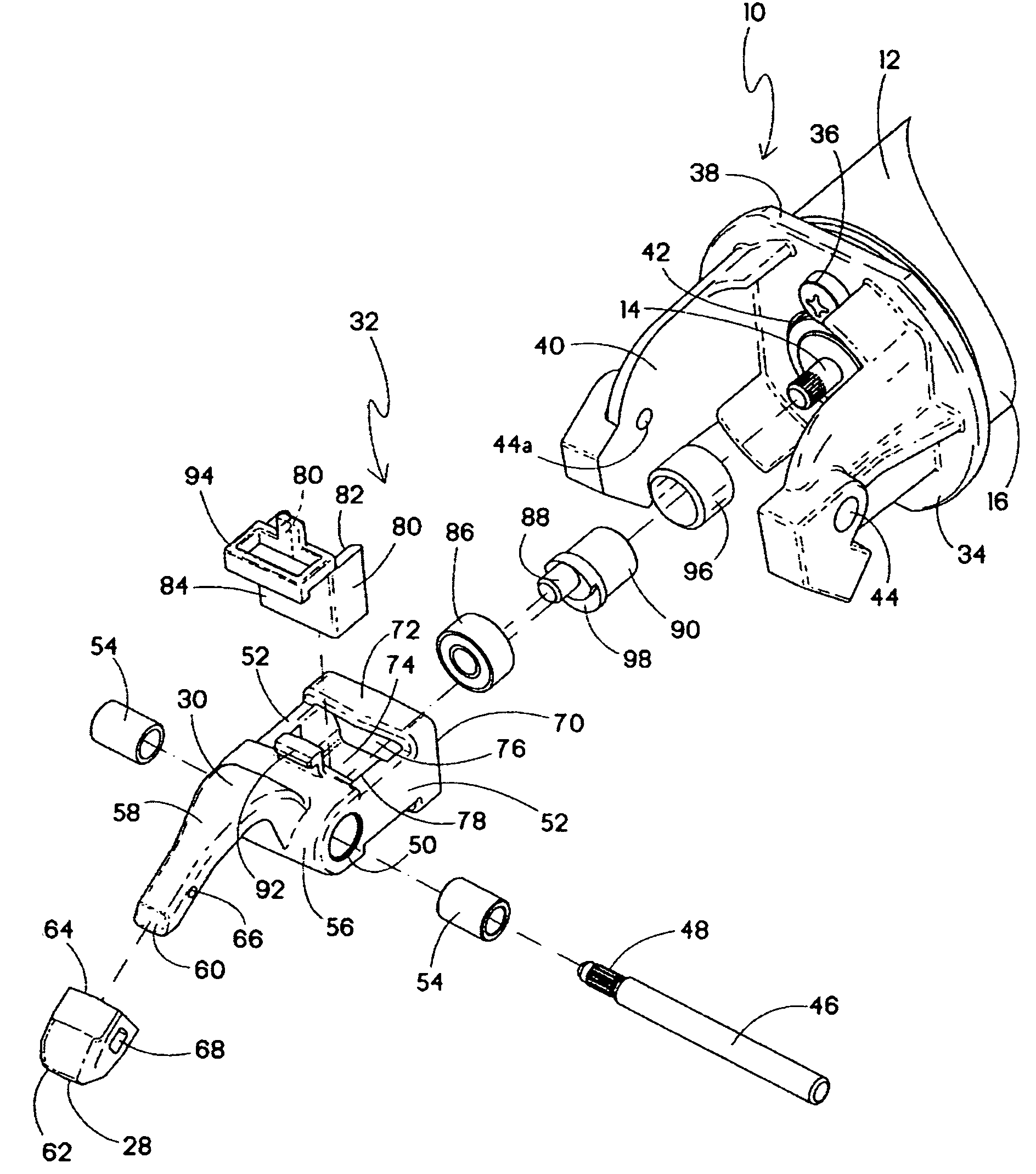
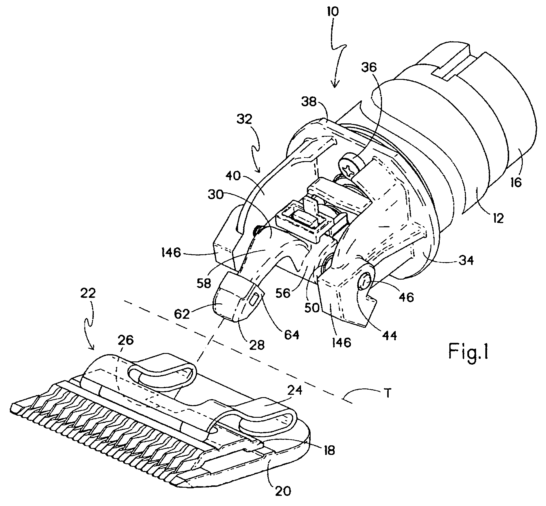
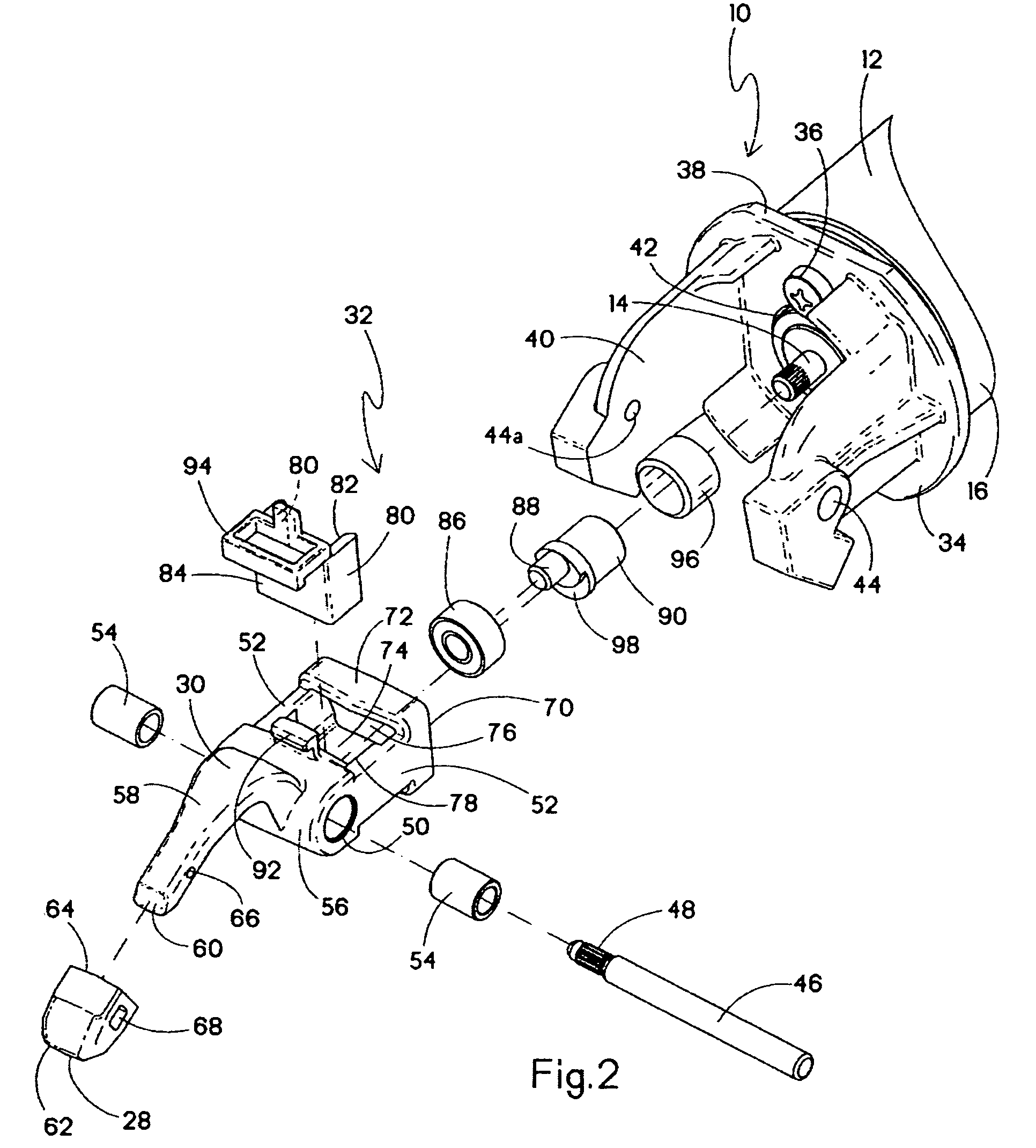
[0017]Referring now to FIGS. 1 and 2, a hair clipper suitable for use with the present drive system is generally designated 10, and includes a motor 12, typically an electric motor powered by battery or line voltage. It will be appreciated that the size and / or type of the motor may vary to suit the application. The motor 12 is designated as a rotary type, having an output shaft 14 (FIG. 2) projecting axially from a motor housing 16. As is well known in the art, rotation of the output shaft 14 must be translated into linear motion in the form of linear reciprocation of a moving blade 18 relative to a stationary blade 20 of a clipper bladeset 22.

[0018]The bladeset 22 typically includes a biasing element 24 in the form of a spring which causes the moving blade 18 to be slidingly biased against the stationary blade 20 for more effective cutting action. In the present embodiment, the moving blade 18 defines a drive recess 26 (shown hidden) for receiving a blade engagement or driving tip ...


PUM


Abstract

A hair clipper includes a motor with a rotary output shaft, a bladeset including a stationary blade and a moving blade configured for reciprocation relative to the stationary blade, a drive system configured for transferring motion from the output shaft to the bladeset, and including a driving member moving linearly along an axis transverse to a longitudinal axis of the clipper.

Description

BACKGROUND OF THE INVENTION[0001]The present invention relates generally to hair cutting devices having a bladeset including a moving blade reciprocating relative to a stationary blade and a drive system for powering the bladeset, and more specifically to hair clippers or trimmers used for cutting hair of humans or animals.[0002]Conventional hair cutting devices using a rotary drive system, such as hair trimmers and clippers typically include a drive member powered by the output shaft of the motor. For the purposes of this application, the terms “hair cutting device”, “hair clipper” and “hair trimmer” are considered interchangeable. The drive system converts rotary motion generated by the motor into linear motion in the form of the reciprocating moving blade relative to the stationary blade.[0003]In most drive systems, a driving end of the drive member follows an arcuate or semi-arcuate path as it engages the moving blade of the bladeset. In this case, the term “semi-arcuate” refers...

Claims


Application Information

Patent Timeline
Patent Type & Authority Patents(United States)
IPC IPC(8): B26B19/02B26B19/28B26B29/06
CPCB26B19/28B26B19/06B26B19/02
Inventor DIRKS, KEITH W.FREAS, JONBUCK, JR., ROBERT N.
Owner WAHL CLIPPER
Why Eureka
Try Eureka