Cooling oil delivery structure for a vehicular generator, and engine including same

a technology for vehicular generators and cooling oil, which is applied in the direction of machines/engines, mechanical energy handling, mechanical equipment, etc., can solve the problems of not easy to form a compact crankcase, increase the manufacturing cost, and never increase the friction resistance of the rotor turning of the generator, so as to achieve uniform and efficient cooling

Inactive Publication Date: 2008-03-25
HONDA MOTOR CO LTD
View PDF20 Cites 19 Cited by
  • Summary
  • Abstract
  • Description
  • Claims
  • Application Information

AI Technical Summary

Benefits of technology

[0012]In the generator cooling oil delivery structure for the vehicular generator according to the first aspect of the invention, the oil jet, for cooling the generator by jetting oil thereto, is provided connected to and extending from a distal end of the piston cooling oil passage, in which intermediate portions of the piston cooling passage are adapted to provide jetted oil for cooling respective pistons. As a result, there is no need to form a dedicated oil passage for exclusively supplying generator-cooling oil to the generator-cooling oil jet. Because a dedicate oil passage for the generator is not required according to the first aspect of the invention, working man-hours are reduced, and the manufacturing cost can be reduced.
[0014]In the cooling oil delivery structure for the vehicular generator according to the second aspect of the invention, the engine speed sensor is arranged adjacent to the space around the generator toward which oil is jetted from the generator-cooling oil jet. As a result, the space toward which oil is jetted from the generator-cooling oil jet can be secured as an area for housing the engine speed sensor, and the generator can therefore be uniformly and efficiently cooled without enlarging the internal combustion engine.

Problems solved by technology

In the structure for cooling the generator disclosed in JP Patent No. 2986470 as described above, a dedicated oil passage is required to be formed in the crankcase to cool the generator, where this oil passage is used only to deliver oil to the oil jet, and thus a process for forming the dedicated passage in the crankcase is required, whereby the manufacturing cost is increased.
In addition, since a path of the oil passage that reaches the required position in which the jet nozzle is arranged is required to be determined in consideration of the overall form and workability of the crankcase, it is not easy to form a compact crankcase which includes the oil passage.
As a result, the space toward which oil is jetted from the generator-cooling oil jet is the space around the generator, and as oil is not jetted directly on to the generator, friction resistance to the turning of the rotor of the generator is never increased.

Method used


Image

  • Cooling oil delivery structure for a vehicular generator, and engine including same
  • Cooling oil delivery structure for a vehicular generator, and engine including same
  • Cooling oil delivery structure for a vehicular generator, and engine including same

Examples


Embodiment Construction

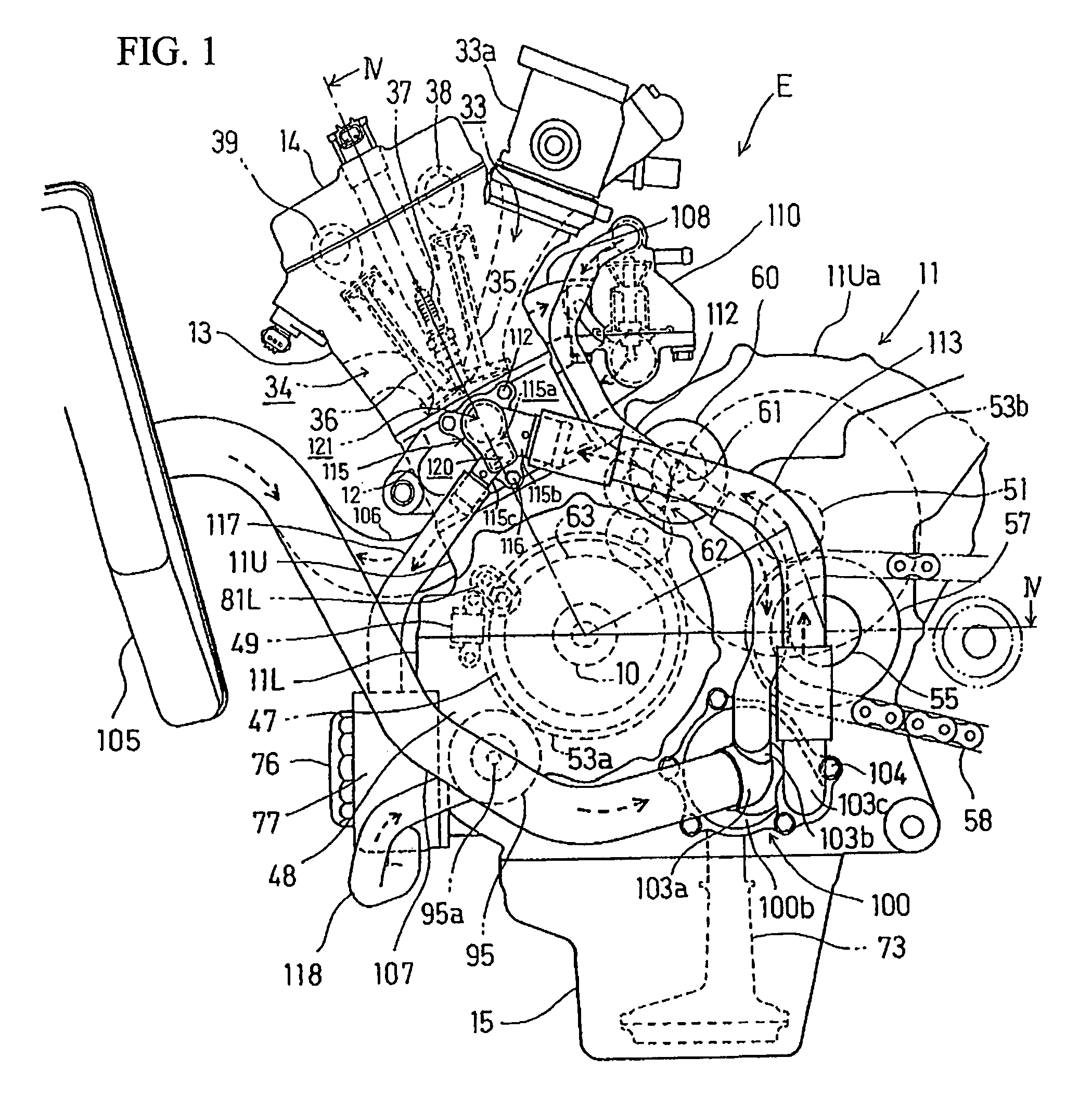
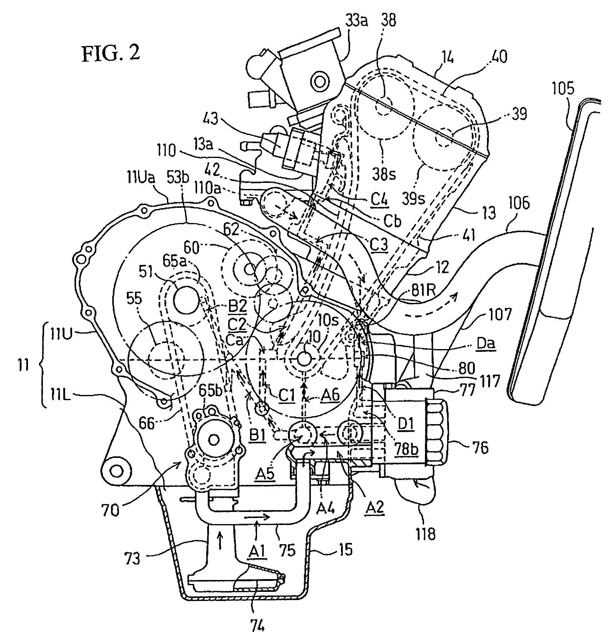
[0029]A selected illustrative embodiment of the invention will now be described in some detail, with reference to FIGS. 1 to 10. It should be understood that only structures considered necessary for clarifying the present invention are described herein. Other conventional structures, and those of ancillary and auxiliary components of the system, are assumed to be known and understood by those skilled in the art.

[0030]The illustrative embodiment of the cooling oil delivery structure for a vehicular generator is described herein in association with an internal combustion engine E. The engine E may, for example, be provided as a four-cylinder in-line, water-cooled internal combustion engine, where the four cylinders are arranged in series, and this engine may be transversely mounted in a motorcycle with a crankshaft 10 directed sideways, transverse to a longitudinal axis of the motorcycle.

[0031]In this specification, a reference to “forward” refers to a forward direction of the vehicle...


PUM


Abstract

In an engine having a generator mounted thereon, an oil passage is formed within the engine's crankcase to supply oil to an oil jet for cooling one or more pistons. In addition, oil is supplied to an oil jet for cooling the generator, using the oil passage in common with the oil supply for cooling the piston, without requiring a separate, dedicated oil passage for the generator. The cooling oil delivery structure is provided for cooling the generator which is located at one end of the crankshaft. The oil passage for cooling pistons, which includes an oil jet for cooling each respective piston by jetting oil to the piston, is arranged on an axis substantially parallel to the crankshaft. A generator-cooling oil jet is provided on the crankcase at a terminal end of, and in fluid communication with the oil passage for cooling the pistons.

Description

CROSS-REFERENCE TO RELATED APPLICATIONS[0001]The present invention claims priority under 35 USC 119 based on Japanese patent application No. 2006-052762, filed on Feb. 28, 2006. The entire subject matter of this priority document, including claims, drawings, and specification is incorporated by reference herein.BACKGROUND OF THE INVENTION[0002]1. Field of the Invention[0003]The present invention relates generally to internal combustion engines equipped with generators. More particularly, the present invention relates to improved structure for cooling a vehicular generator mounted on an internal combustion engine, by splashing the generator internally with cooled engine oil from the engine's oiling system.[0004]2. Description of the Background Art[0005]It is known in the art to provide a cooling structure for a generator in a vehicle. In one example of a previously known cooling structure for a vehicular generator, oil is sprayed on an outer rotor of the generator by jetting oil towa...

Claims


Application Information

Patent Timeline
Patent Type & Authority Patents(United States)
IPC IPC(8): F01P1/06H02K9/00
CPCF01M1/08F01P3/08H02K7/1815H02K9/19F01P3/06F02F2007/0041F02F2007/0063
Inventor NAGAHASHI, YOSHIKIYONEYAMA, MASAKIKONO, NAOKIMINAMI, KOHJI
Owner HONDA MOTOR CO LTD
Why Eureka
Try Eureka