Braze material for an attack tool

a cutting element and material technology, applied in cutting machines, cutting machines, construction, etc., can solve the problems of reducing or eliminating the effectiveness of cutting elements, reducing or eliminating the effect of cutting elements, and often affecting the cutting effect of inserts

Active Publication Date: 2008-03-25
SCHLUMBERGER TECH CORP
View PDF81 Cites 60 Cited by
  • Summary
  • Abstract
  • Description
  • Claims
  • Application Information

AI Technical Summary

Benefits of technology

[0013]The first cemented metal carbide segment may have a diameter of 9 to 13 mm and may have a height of 2 to 6 mm. The carbide segm

Problems solved by technology

Such inserts are often subjected to intense forces, torques, vibration, high temperatures and temperature differentials during operation.
As a result, stresses within the structure may begin to form.
Drill bits for example may exhibit stresses aggravated by drilling anomalies during well boring operations such as bit whirl or spalling often resulting in delamination or fracture of the ab

Method used


Image

  • Braze material for an attack tool
  • Braze material for an attack tool
  • Braze material for an attack tool

Examples


Embodiment Construction

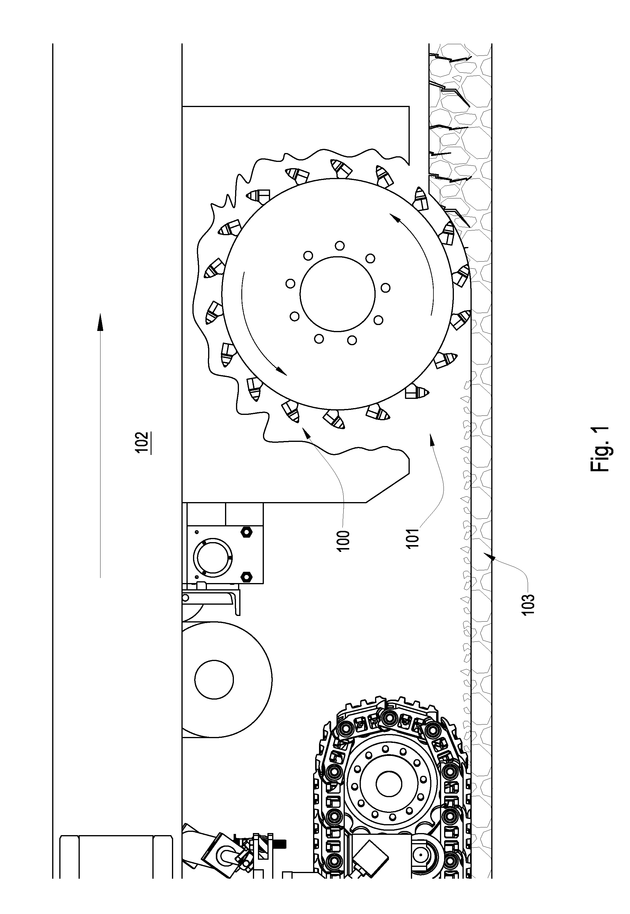
[0029]FIG. 1 is a cross-sectional diagram of an embodiment of attack tools 100 on a rotating drum 101 attached to a motor vehicle 102. The motor vehicle 102 may be a cold planer used to degrade manmade formations such as pavement 103 prior to the placement of a new layer of pavement. In other embodiments the motor vehicle may be a mining vehicle used to degrade natural formations or an excavating machine. Tools 100 may be attached to a drum 102 as shown or in other embodiments a chain may be used. As the drum or chain rotate so the tools 100 engage the formation and thereby degrade it. The formation may be hard and / or abrasive and cause substantial wear on prior art tools. The wear-resistant tool 100 of the present invention may be selected from the group consisting of drill bits, asphalt picks, mining picks, hammers, indenters, shear cutters, indexable cutters, and combinations thereof.

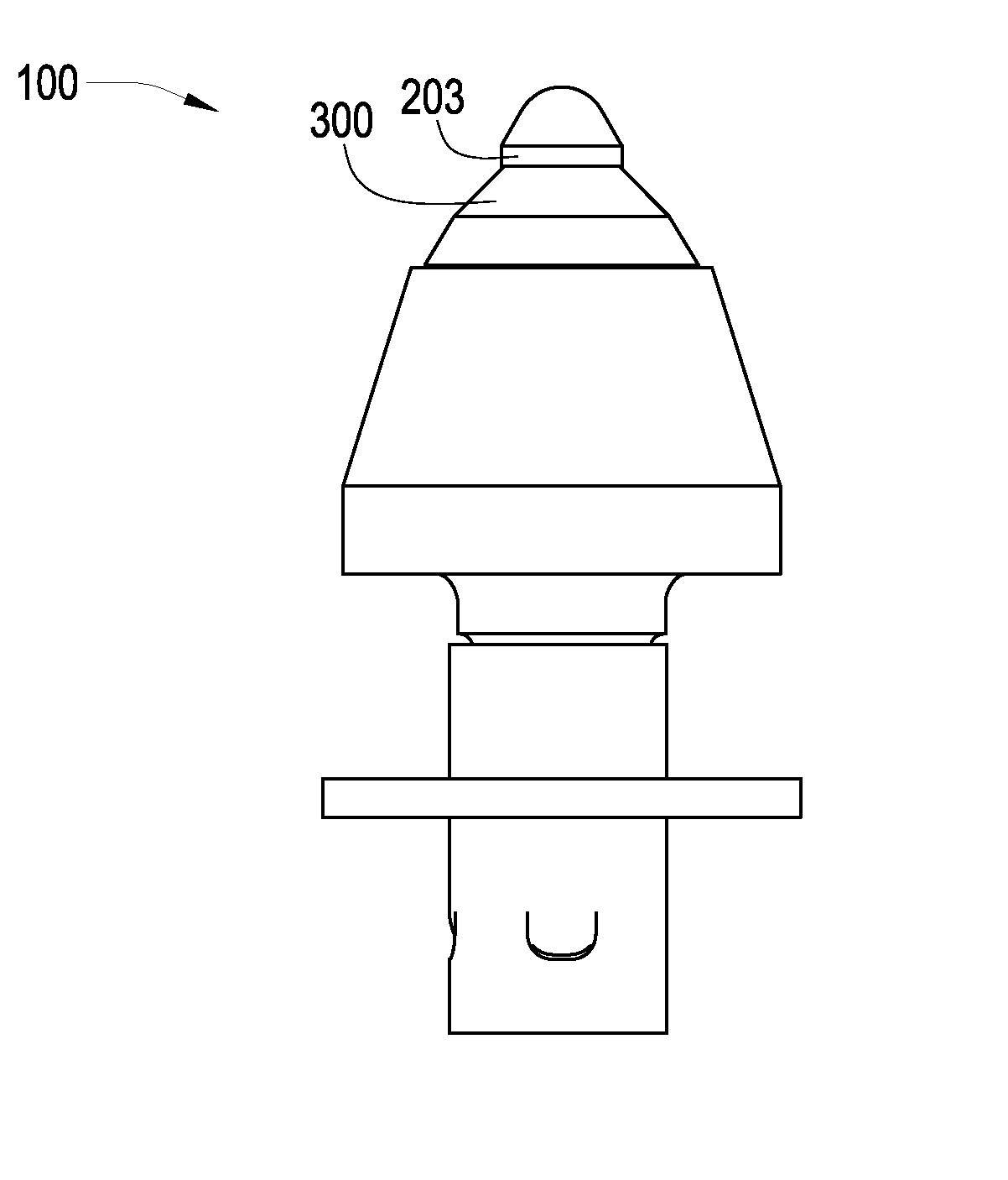
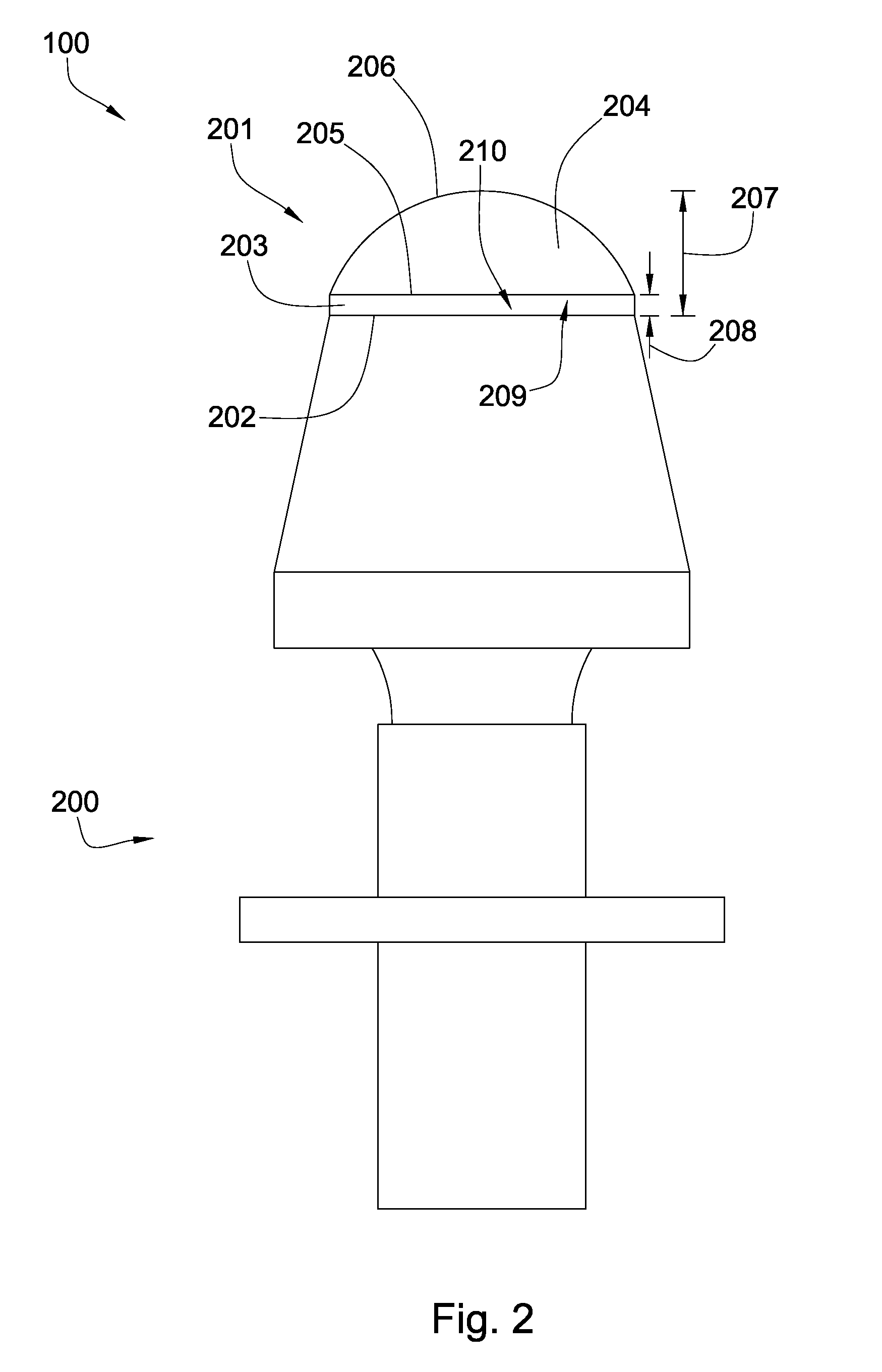
[0030]FIG. 2 is an orthogonal diagram of an embodiment of an attack tool 100 comprising a base 20...


PUM


Abstract

In one aspect of the invention, a tool has a wear-resistant base suitable for attachment to a driving mechanism and also a hard tip attached to an interfacial surface of the base. The tip has a first cemented metal carbide segment bonded to a superhard material at a non-planar interface. The tip has a height between 4 and 10 mm and also has a curved working surface opposite the interfacial surface. A volume of the superhard material is about 75% to 150% of a volume of the first cemented metal carbide segment.

Description

CROSS REFERENCE TO RELATED APPLICATIONS[0001]This application is a continuation of U.S. patent application Ser. No. 11 / 668,254 filed on Jan. 29, 2007 and entitled A Tool with a Large Volume of a Superhard Material. U.S. patent application Ser. No. 11 / 668,254 is a continuation-in-part of U.S. patent application Ser. No. 11 / 553,338 which was filed on Oct. 26, 2006 and was entitled Superhard Insert with an Interface. All of the above mentioned patent applications are herein incorporated by reference for all that they contain.BACKGROUND OF THE INVENTION[0002]The invention relates to an improved cutting element or insert that may be used in machinery such as crushers, picks, grinding mills, roller cone bits, rotary fixed cutter bits, earth boring bits, percussion bits or impact bits, and drag bits. More particularly, the invention relates to inserts comprised of a cemented metal carbide segment with a non-planar interface and an abrasion resistant layer of a superhard material affixed th...

Claims


Application Information

Patent Timeline
IPC IPC(8): E21B10/36
CPCE21B10/5735E21C35/183
Inventor HALL, DAVID R.CROCKETT, RONALDJEPSON, JEFF
Owner SCHLUMBERGER TECH CORP
Why Eureka
Try Eureka