Method of manufacturing a face plate for a golf club head

a manufacturing method and golf club technology, applied in the field of golf clubs, can solve the problems and achieve the effect of saving substantial time and money and great uniformity

Active Publication Date: 2008-03-25
KARSTEN MFG CORP
View PDF15 Cites 207 Cited by
  • Summary
  • Abstract
  • Description
  • Claims
  • Application Information

AI Technical Summary

Benefits of technology

[0004]According to the present invention, a golf club head is manufactured by removing a portion of the rear surface of a face plate to form a central thickened region surrounded by a transition region that tapers to a thinner peripheral region. According to the illustrative embodiment, the face plate is a rolled sheet titanium alloy between 0.130 and 0.180 inches thick, a portion of the transition region of which is machined away to leave the central thickened region and to form the transition region and the thinner peripheral region. Rather than forming the rear surface contour of the face plate by making multiple passes with an end mill, however, the central portion, the transition region and the peripheral region are formed in a single elliptical pass with a special cutting tool. The cutting tool, or “form cutter” has a conical lateral cutting surface, which forms the transition region and the peripheral region in a single operation. Use of this form cutter to machine the transition region and peripheral region in a single operation yields greater uniformity in the rear surface contour of the face plate and saves substantial time and money over prior art multiple pass machining operations.

Problems solved by technology

Use of this form cutter to machine the transition region and peripheral region in a single operation yields greater uniformity in the rear surface contour of the face plate and saves substantial time and money over prior art multiple pass machining operations.

Method used


Image

  • Method of manufacturing a face plate for a golf club head
  • Method of manufacturing a face plate for a golf club head
  • Method of manufacturing a face plate for a golf club head

Examples


Embodiment Construction

[0013]The drawing figures are intended to illustrate the general manner of construction and are not necessarily to scale. In the description and the in the drawing figures, specific illustrative examples are shown and herein described in detail. It should be understood, however, that the drawing figures and detailed description are not intended to limit the invention to the particular form disclosed but are merely illustrative and intended to teach one of ordinary skill how to make and / or use the invention claimed herein and for setting forth the best mode for carrying out the invention.

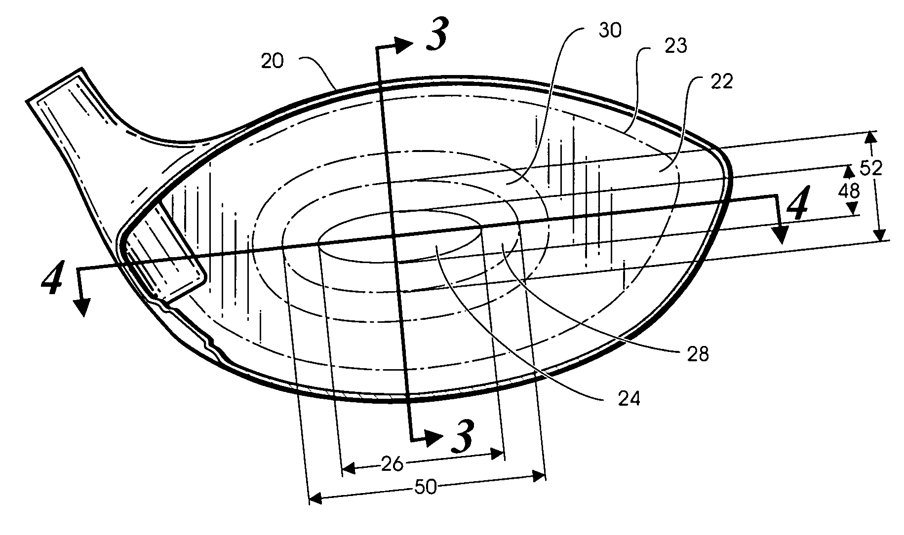
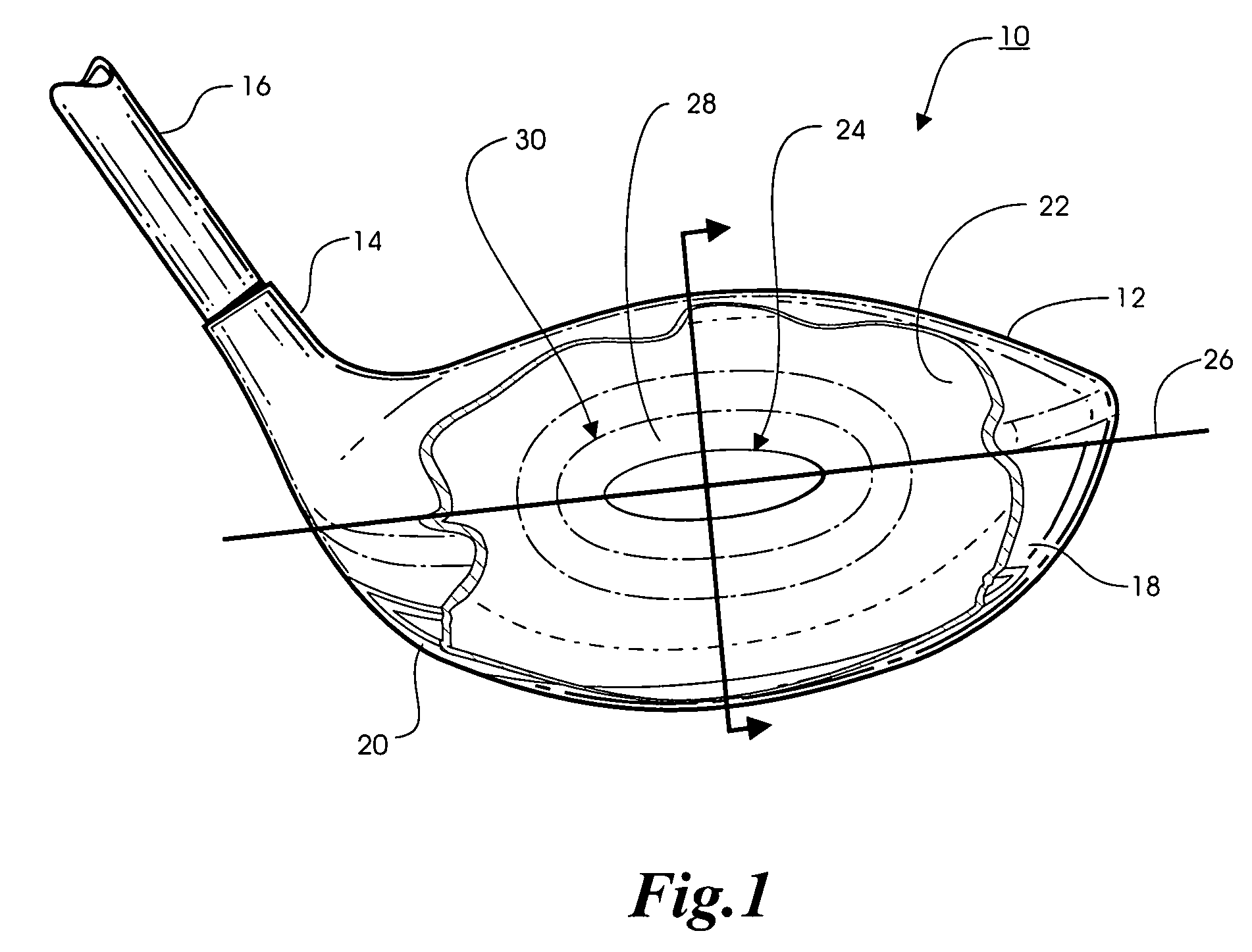
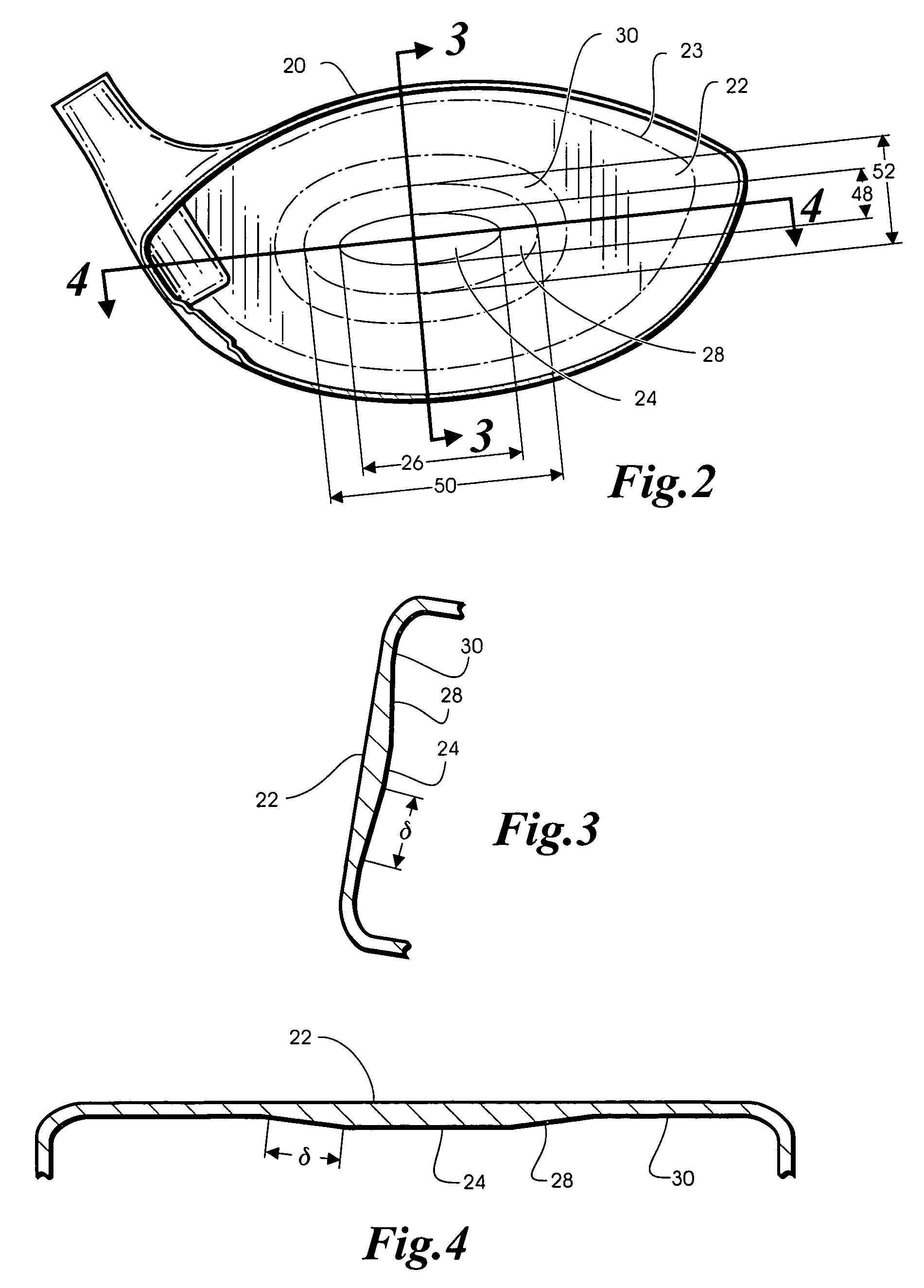
[0014]Referring to FIG. 1, a golf club 10 includes a head 12, a hosel 14 and a shaft 16. Head 12 includes a hollow body 18 made of a metal material such as titanium. Hollow body 18 is formed as a shell 20, which may be assembled from a series of forged pieces but, in the illustrative embodiment, comprises a titanium investment casting. A face plate 22 is attached by conventional means such as plasma ...


PUM


Abstract

A golf club is manufactured by machining away a portion of the rear surface of a club face blank to form an elliptical central thickened region that tapers through a transition region to a thinner peripheral region. The elliptical central thickened region, transition region and the portion of the peripheral region surrounding the raised portion are formed in a single elliptical pass with a special cutting tool. The cutting tool, or “form cutter” has a conical lateral cutting surface, which forms the sloped transition region and the peripheral region surrounding it in a single operation.

Description

BACKGROUND OF THE INVENTION[0001]This invention relates generally to golf clubs and, in particular, to so-called metal wood drivers.[0002]Recent developments in golf club design have included improvements in drivers, which are clubs used primarily to strike a golf ball resting on a golf tee. These improvements have resulted in drivers with club heads consisting of a hollow shell usually made of metal, such as steel, aluminum, or titanium. These hollow shells have relatively thin walls including a thin front wall that is used to impact the golf ball. In order to prevent the front wall of these hollow shells from permanently deforming or cracking upon ball impact, it has become necessary to reinforce the front wall. One example of a golf club head consisting of a hollow metal shell with a reinforced front wall is disclosed in U.S. Pat. No. 4,511,145 to Schmidt. The club head disclosed in the Schmidt patent has an arched ridge extending between the heel and toe ends of the front wall. ...

Claims


Application Information

Patent Timeline
Patent Type & Authority Patents(United States)
IPC IPC(8): A63B53/04B21K17/00
CPCA63B53/0466A63B53/04B23C3/13A63B2053/0462A63B2053/0416A63B2053/0458Y10T407/1946Y10T29/49Y10T29/49826Y10T409/303752Y10T29/49995A63B53/0462Y10T83/0304A63B60/00A63B53/0408A63B53/0416A63B53/0458
Inventor SCHWEIGERT, BRADLEY D.
Owner KARSTEN MFG CORP
Why Eureka
Try Eureka