Holder for optical modules, optical module and optical connector

a technology for optical modules and connectors, applied in the field of optical module holders, can solve the problems of uneven thickness of the holder, poor operation efficiency, uneven deformation of the holder, etc., and achieve the effect of reducing uneven deformation

Inactive Publication Date: 2008-03-25
ENPLAS CORP
View PDF8 Cites 11 Cited by
  • Summary
  • Abstract
  • Description
  • Claims
  • Application Information

AI Technical Summary

Benefits of technology

[0014]According to the present invention, an optical module holder that can reduce uneven deformation caused by molding shrinkage, even when the optical module holder is formed integrally with a lens, is provided.

Problems solved by technology

The alignment is difficult and, therefore, operating efficiency is poor.
However, as in Patent Literature 2, in the optical module including the holder formed integrally with the lens, the thickness of the holder is uneven.
Thin areas are pulled by thick areas due to mold shrinkage, and the holder is unevenly deformed.
In particular, the lens area to be the optical path becomes thicker than other areas, increasing the uneven deformation caused by mold shrinkage.
As a result, the optical performance of the optical module may be degraded because of such uneven deformation.

Method used


Image

  • Holder for optical modules, optical module and optical connector
  • Holder for optical modules, optical module and optical connector
  • Holder for optical modules, optical module and optical connector

Examples


first embodiment

[0036]A first embodiment of an optical module holder according to the present invention will be described in detail hereinafter, with reference to the attached drawings.

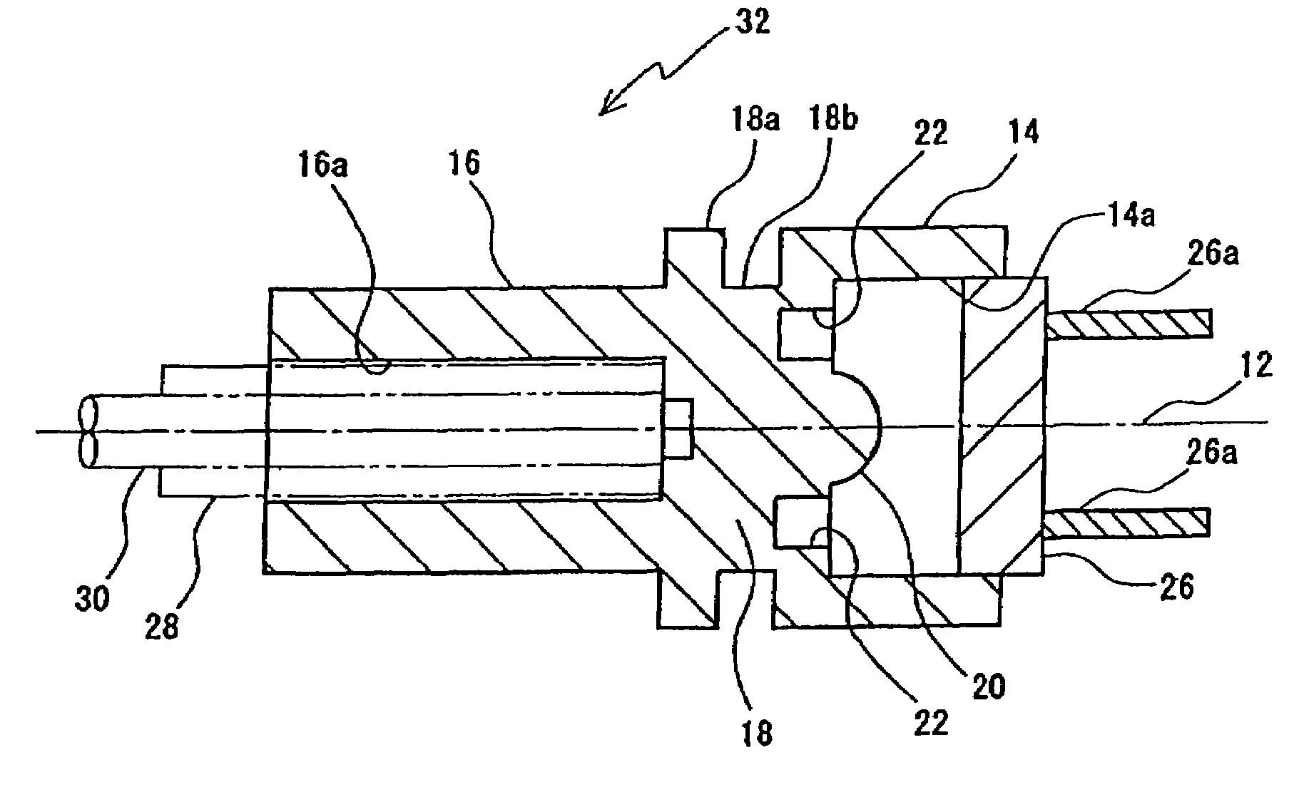
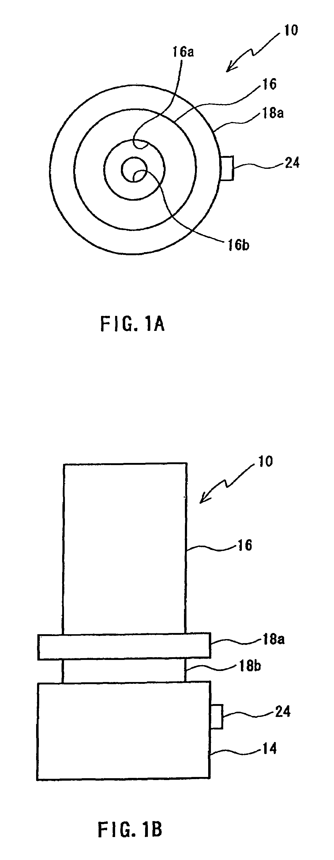
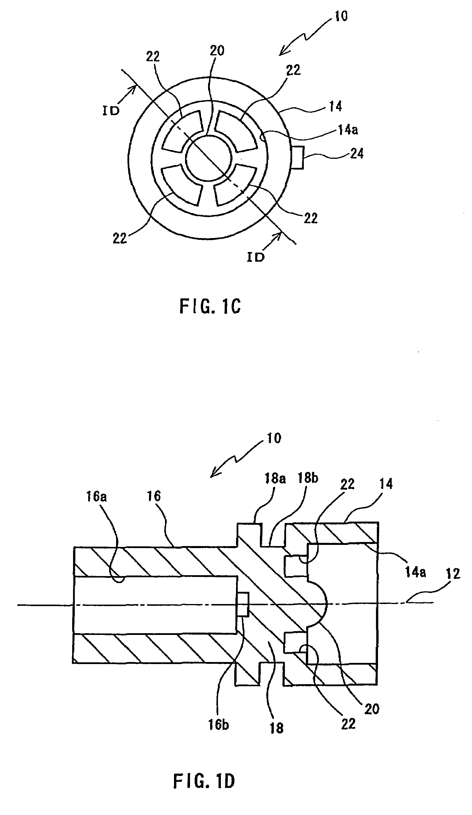
[0037]FIG. 1A to FIG. 1D show a first embodiment of an optical module holder according to the present invention. An optical module holder 10 according to the present embodiment is formed integrally by injection molding of transparent resin material, such as polyetherimide (PEI), polycarbonate (PC), or polymethylmethacrylate (PMMA). As shown in FIG. 1A to FIG. 1D the optical module holder 10 includes a cylindrical first cylinder section 14, a cylindrical second cylinder section 16, and a discoid partition wall section 18. The first cylinder section 14 and the second cylinder section 16 are respectively disposed surrounding an axis 12 (refer to FIG. 1D) (so that the axis 12 is the center line) and extend in a direction along the axis 12. The partition wall section 18 is disposed between the first cylinder section 14 an...

second embodiment

[0062]Next, a second embodiment of the optical module holder according to the present invention will be explained in detail.

[0063]Components having the same or similar basic configuration as those in the first embodiment are given the same reference number and described.

[0064]FIG. 9A and FIG. 9B show the second embodiment of the optical module holder according to the present invention. An optical module holder 15 according to the present embodiment is formed integrally, as in the first embodiment, by injection molding of resin material. The optical module holder 15 compresses the first cylinder section 14, the second cylinder section 16, and the partition wall section 18.

[0065]However, in the optical module holder 15 according to the present embodiment, the formation position of the concave section (grooved section) differs from that in the first embodiment.

[0066]In other words, as shown in FIG. 9A, the g concave section 27 (grooved section) according to the present embodiment is di...


PUM


Abstract

An optical module holder in which an optical transmission line attaching section for attaching an end section of a light transmission line, a photoelectric element attaching section for attaching a photoelectric element including at least one of a light-emitting element or a light-receiving element, and a wall section connecting the optical transmission line attaching section and the photoelectric element attaching section are formed integrally, and a lens for optically joining the photoelectric element and the optical transmission line is formed integrally with the wall section, so that the convex surface of the lens is on the photoelectric element side, facing the photoelectric element attached to the photoelectric attaching section, wherein one or a plurality of concave sections are formed as grooved sections on the wall section so as to surround the lens.

Description

BACKGROUND OF THE INVENTION[0001]1. Field of the Invention[0002]The present invention relates to an optical module holder used in optical fiber communication. In particular, the present invention relates to an optical module holder, an optical module, and an optical connector, in which the optical module is formed integrally with a lens.[0003]2. Description of the Related Art[0004]In recent years, with the increase in the speed and capacity of data communication, the demand for optical fiber communication technology using optical fiber is rising. In such optical fiber communication, the transmitting end converts a signal to be transmitted to an electrical signal. An optical signal formed from light emitted from a light source for communication, such as a semiconductor laser or a light-emitting diode, is transmitted to the receiving end by an optical fiber transmission line, according to the electrical signal. Alight detector receives the transmitted optical signal and converts the o...

Claims


Application Information

Patent Timeline
Patent Type & Authority Patents(United States)
IPC IPC(8): H01J40/14H01J5/02
CPCG02B6/4204G02B6/4239
Inventor MOGI, TOSHIYUKISHITO, KAZUTAKAKAMITAKAHARA, TAKASHINAKAMURA, TAKAYUKI
Owner ENPLAS CORP
Why Eureka
Try Eureka