System and method for distributed facility management and operational control

a technology for distributed facilities and operational control, applied in adaptive control, program control, instruments, etc., can solve problems such as inability to integrate and manage multiple systems, large network situations and solutions, and difficult interoperability

Active Publication Date: 2008-03-25
CISCO TECH INC +1
View PDF12 Cites 444 Cited by
  • Summary
  • Abstract
  • Description
  • Claims
  • Application Information

AI Technical Summary

Benefits of technology

[0009]An environmental control system is configured for use in connection with a multi-facility enterprise. The system comprises a microprocessor-based control host, and a multiplicity of disparate environmental control devices, each control device operatively responsive to monitoring and control commands delivered in accordance with one of a plurality of disparate communication protocols. A multiplicity of I/O ports is coupled between the control host and the multiplicity of control devices, the I/O ports including a plurality of communication bus implementations. A configuration database, includes a set of configuration files, each configuration file further comprising an identification of monitoring and control commands corresponding to each of the multiplicity of disparate environmental control devices.
[0010]An operational instruction set, the control host operatively responsive thereto, controls monitoring and operation of the multiplicity of disparate environmental control devices by determining an appropriate configuration for each control device and communicates corresponding monitoring and control commands to each device in accordance with its corresponding communication protocol over a selected I/O port.
[0011]In one particular aspect, the configuration files further comprise a set of personality module files, the personality modu

Problems solved by technology

However, this broad network capability often means that the variety of networking situations and solutions is quite large and compatibility between networks, and even various systems within networks, is problematic to say the least.
The systems range from simple voltage and/or current meters to very complex HVAC control systems.
Most are offered by different manufacturers and have different communication protocols, installation requirements, and the like, making interoperability substantially impossible.
Indeed, most building automation system customers are quite dissatisfied because their di

Method used


Image

  • System and method for distributed facility management and operational control
  • System and method for distributed facility management and operational control
  • System and method for distributed facility management and operational control

Examples


Embodiment Construction

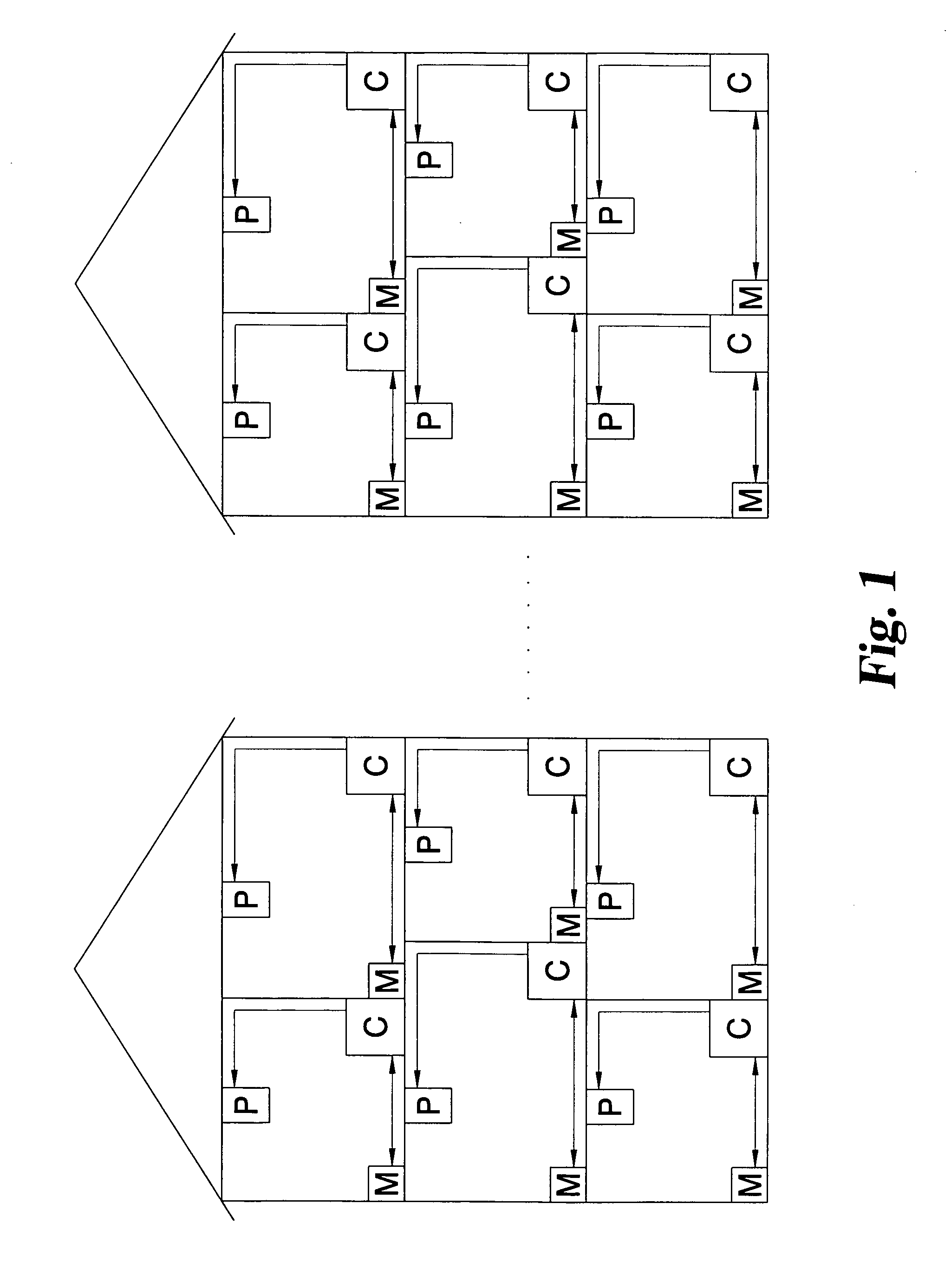
[0035]With regard to the exemplary illustration of FIG. 1, conventional facilities installations are inherently problematic for interoperability purposes because of the number of different apparatus and systems that must be controlled by any type of facilities management device. In the exemplary facility of FIG. 1, a building 10 is illustrated as having a couple of facilities implementations; a physical lighting plant and an HVAC plant disposed about its various floors. Many commercial buildings have a variety of tenants with different operational requirements and power usage (watts per square foot) typical examples include computer centers and phone switching systems (or other electrical operations) with additional cooling loads and much higher electrical energy usage per square foot. If tenants utilize additional operating time (for example on a weekend) the building proprietor needs to determine the additional cost of operating the tenant's space and any HVAC systems required for...


PUM


Abstract

An environmental control system controls monitoring and operation of a multiplicity of disparate environmental control devices by determining an appropriate configuration for each control device and communicates corresponding monitoring and control commands to each device in accordance with its corresponding communication protocol over a selected I/O port. An operational instruction set includes a structural definition of an enterprise facility in which devices are defined by personality modules and communicate with a system host in accordance with a protocol defined in a protocol module. Facility implementation is defined by a node tree structure which collects suitable protocol nodes under a corresponding I/O interface port node. Device (personality) nodes are collected under corresponding protocol nodes, and data point nodes depend from their corresponding device nodes. Data points nodes are individually accessible by merely traversing the node tree using a URL-like notational structure, allowing off-site users to control and monitor environmental devices by issuing commands in the form of a URL.

Description

CROSS REFERENCE TO RELATED APPLICATION[0001]The present application is related to and take priority from U.S. Provisional Patent Application Ser. No. 60 / 355,190, filed Feb. 7, 2002, entitled “System And Method For Distributed Facility Management And Operational Control,” commonly owned by the assignee of the present invention, the entire contents of which are expressly incorporated herein by reference.FIELD OF THE INVENTION[0002]The present invention is directed to systems and methods for computerized facility management and, more particularly, to a multiple-protocol presentation and management interface for multiple devices and systems within a facility.BACKGROUND OF THE INVENTION[0003]The last couple of decades have witnessed a revolution in electronic connectivity and communication technology, particularly when communication and control devices are associated with wide area networks, such as the Internet. Technology has proceeded from a point where simple, stand-alone computer sy...

Claims


Application Information

Patent Timeline
IPC IPC(8): G05B13/00
CPCG05B19/042G05B2219/25061G05B2219/25168
Inventor CRUSE, MIKE B.
Owner CISCO TECH INC
Why Eureka
Try Eureka