Control device of cylinder reducing operation of multi-cylinder engine

a control device and engine technology, applied in the direction of electric control, machines/engines, output power, etc., to achieve the effect of reducing operation, ensuring engine operation stability, and comfortable drivability of vehicles

Active Publication Date: 2008-04-01
TOYOTA JIDOSHA KK
View PDF29 Cites 54 Cited by
  • Summary
  • Abstract
  • Description
  • Claims
  • Application Information

AI Technical Summary

Benefits of technology

[0010]According to the present invention, there is provided a novel control device of cylinder reducing operation for a multi-cylinder engine, controlling an operation mode of the engine more appropriately for fuel economy while ensuring the operational stability of the engine and comfortable drivability of a vehicle.
[0013]In the present invention, however, since engine output torque is directly monitored, the judgment of the switching of an operation mode can be done when an actually generated output power level reaches to the level to be executed in the reduced cylinder mode or the normal mode (around the maximum level available in the reduced cylinder mode), thereby ensuring the generation of torque / power requested in operating an engine while saving fuel. In other words, the switching of an operation mode into the reduced cylinder mode will be done without unexpected lack of torque / power while saving fuel as much as possible, irrespective of the variation of the conditional and / or environmental parameters of the engine. Especially for a hybrid driving system having an internal combustion engine and dynamotors, where a target value of torque or power to be generated is determined with an input device, e.g. an accelerator pedal of a driver, the direct monitoring of the output torque solely from the engine makes it easy to adjust the total output power (from the engine plus dynamotors) to the target level.
[0014]In the inventive device, when an output shaft of a multi-cylinder engine is operationally linked to a dynamotor e.g. through a planetary gear, a dynamotor may be useful as the detector detecting engine output torque. In a hybrid driving system where the output shaft of an internal combustion engine is operationally linked to an electric motor and an electric generator and wheels of a vehicle are driven with a shaft of the planetary gear linked to the motor, the torque detector will be the electric generator. In this case, the engine output torque can be detected precisely from reaction torque on the generator during driving the wheels. In this regard, as noted, upon the switching of an operation mode, an abrupt variation or a surge in torque is generated due to the variation of the mass of motion of an engine accompanied by the transient variation of engine revolution. In order to avoid transient variation of torque and revolution, the output torque may be modified for following its target value, e.g. by operating the electric motor or generator. The direct monitoring of the actual output torque makes the torque modification much easier.
[0017]Thus, it is an object of the present invention to provide new and novel control devices for cylinder reducing operation for a multi-cylinder engine, enabling the switching of an operation mode at a more appropriate timing than ever, and thereby allowing reduced cylinder operation to the full extent while ensuring the generation of required output torque and improving fuel economy.
[0018]It is another object of the present invention to provide such devices directly monitoring the output torque from an engine, and thereby avoiding unexpected shortage of output torque / power upon the switching of the operation mode due to the variation of environmental conditions of the engine.
[0019]It is a further object of the present invention to provide such devices wherein, through monitoring actual output torque from an engine, the transient variation of torque or power is modified for preventing any mechanical shock on an engine system or a vehicle body equipped therewith.

Problems solved by technology

Thus, the judgment of an operation mode between full cylinder and reduced cylinder operations based upon a map employing an intake air amount or a throttle opening as in the conventional control devices is often inappropriate: the switching is not always executed at a power level to be executed in the reduced cylinder mode.

Method used


Image

  • Control device of cylinder reducing operation of multi-cylinder engine
  • Control device of cylinder reducing operation of multi-cylinder engine
  • Control device of cylinder reducing operation of multi-cylinder engine

Examples


Embodiment Construction

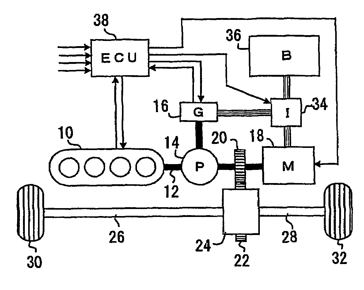
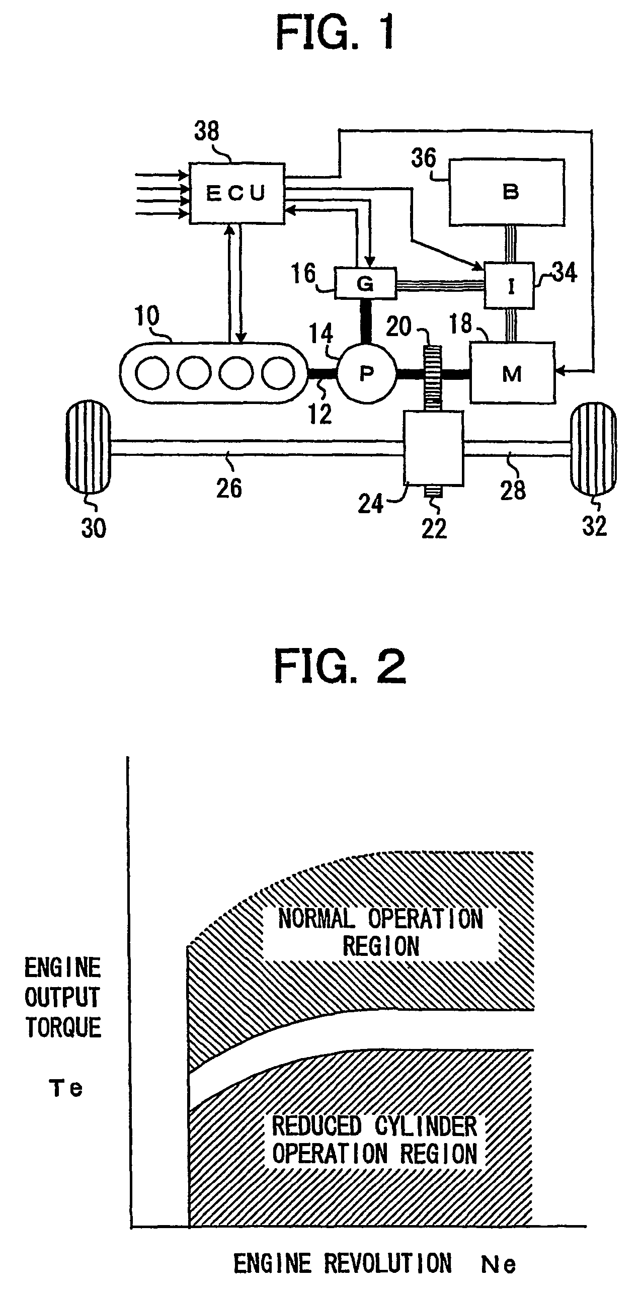
[0026]FIG. 1 shows a diagram of a hybrid driving system for a vehicle, having a multi-cylinder internal combustion engine 10 and dynamotors 16 and 18, cooperating to generate power appropriately determined under the control of Electronic Control Unit (ECU) 38. A control device for cylinder reducing operation of a preferred embodiment according to the present invention is implemented in Electronic Control Unit (ECU) 38 by installing appropriate software.

[0027]In the illustrated system, an output shaft (crank shaft) 12 of the engine 10 is linked to one of three rotational elements of a planetary gear 14, and the other two rotational elements of the planetary gear each are linked to an electric generator (dynamotor G) 16 and an electrical motor (dynamotor M) 18, respectively. A gear 20, mounted on the linkage between the planetary gear 14 and motor 18, engages a gear 22, through which the rotation from the planetary gear 14 (the crankshaft 12) and motor 18 is transmitted to a different...


PUM


Abstract

A control device for cylinder reducing operation of a multi-cylinder engine for a vehicle controls the number of working cylinders in the engine more appropriately for fuel economy while ensuring the operational stability of the engine and comfortable drivability of the vehicle. The control device comprises a detector detecting engine output torque and judges if cylinder reducing operation is to be executed while referring to the engine output torque. Because of the detection of engine output torque, cylinder reducing operation will be executed as long as torque requested of the engine is available from the reduced number of working cylinders, thereby ensuring the generation of torque required in operating the engine while saving fuel as much as possible. Through a learning process, criteria for the judgment of execution of cylinder reducing operation are modified to be adapted for any variation of engine output performances.

Description

BACKGROUND OF THE INVENTION[0001]1. Field of the Invention[0002]The present invention relates to a control system for a multi-cylinder internal combustion engine, and more specifically, to a system for controlling the number of working (active) cylinders in a multi-cylinder engine and its operation.[0003]2. Description of Prior Art[0004]For improvement of fuel economy in multi-cylinder internal combustion engines for vehicles such as automobile, there has been proposed a strategy for controlling the number of working cylinders in an engine, depending upon a load applied thereon. A multi-cylinder engine has higher energy efficiency (the ratio of outputted mechanical energy to inputted fuel energy) when a load per cylinder is high. Thus, in this strategy, some of cylinders, e.g. a half number of cylinders, in an engine are selectively rendered inactive and a load per working cylinder is increased when the total load on the engine is low. This operation of a multi-cylinder engine while...

Claims


Application Information

Patent Timeline
Patent Type & Authority Patents(United States)
IPC IPC(8): F02D13/06B60W20/00B60K6/445B60L50/16B60W10/06F02D17/02F02D29/02F02D29/06F02D35/00F02D41/14F02D41/24F02D41/36F02D45/00
CPCB60K6/365B60K6/445B60W10/06F02D17/02F02D29/06F02D41/1497F02D41/2451F02D41/0087B60W2550/12Y10T477/23F02D2250/18F02D2250/21F02D2250/24Y02T10/6239B60W2555/20Y02T10/62
Inventor TAKAOKA, TOSHIFUMIAKIYAMA, TADASHISUZUKI, TAKASHIINOUE, TOSHIO
Owner TOYOTA JIDOSHA KK
Why Eureka
Try Eureka