Hybrid drive assembly for a vehicle, in particular a scooter

a technology for hybrid vehicles and drive assemblies, which is applied in the direction of hybrid vehicles, propulsion by batteries/cells, cycles, etc., can solve the problems of low efficiency of combustion engines, relatively high noise levels, and harmful emissions of engines

Active Publication Date: 2008-04-01
UNIV DI PISA +1
View PDF12 Cites 25 Cited by
  • Summary
  • Abstract
  • Description
  • Claims
  • Application Information

AI Technical Summary

Benefits of technology

[0012]It is an object of the present invention to provide an extremely straightforward, low-cost, compact hybrid drive assembly, which can also be used in small, low-cost road vehicles, such as scooters, but which also permits selection of a number of operating modes on the basis of different operating requirements or road conditions.

Problems solved by technology

On the other hand, a combustion engine produces harmful emissions, can only operate within a given speed range, thus requiring the use of auxiliary components (gearbox and clutch), and has a relatively high noise level.
Moreover, even within the operating range, the efficiency of a combustion engine is fairly low (about 20-30%), and variations in the steady-state operation of the engine considerably increase pollutant emissions.
Application in road vehicles, however, has so far been impaired by the limited range of the electric batteries currently available, at least those of a size, weight and cost feasible for earth vehicles.
Known hybrid drive assemblies of the type briefly described above are complex, expensive, and bulky, which is why, to the Applicant's knowledge, they have never been marketed for compact, low-cost vehicles, such as scooters.
Besides being considerably complex and thus not adapted for use in small road vehicles such as scooters, the above-referenced known hybrid drive assembly has a drawback in that the electric machine is located upstream from the transmission unit, and in particular the CVT, so that, when the electric machines operates as a generator (regenerative brake), energy recovery efficiency is reduced.

Method used


Image

  • Hybrid drive assembly for a vehicle, in particular a scooter
  • Hybrid drive assembly for a vehicle, in particular a scooter
  • Hybrid drive assembly for a vehicle, in particular a scooter

Examples


Embodiment Construction

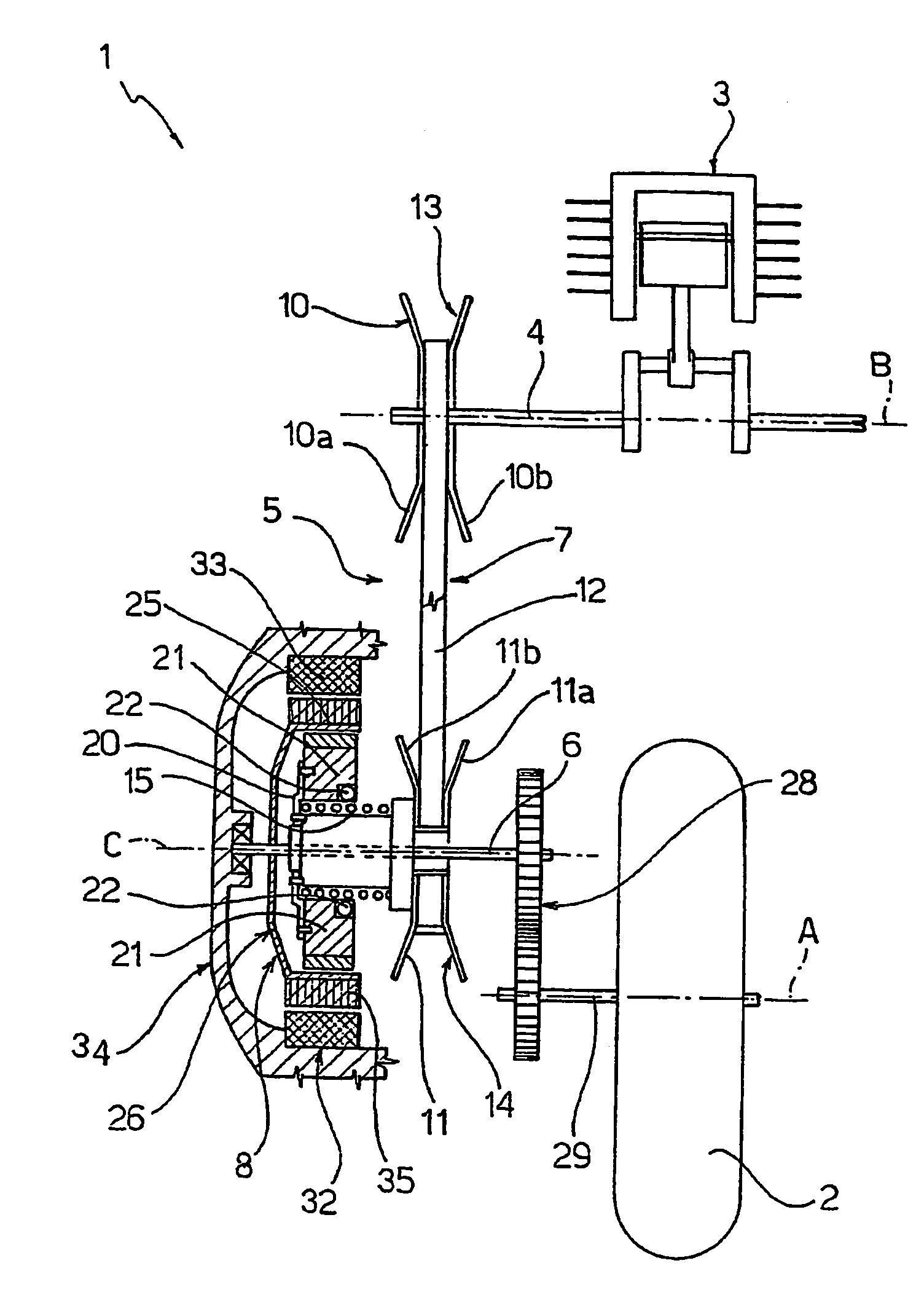
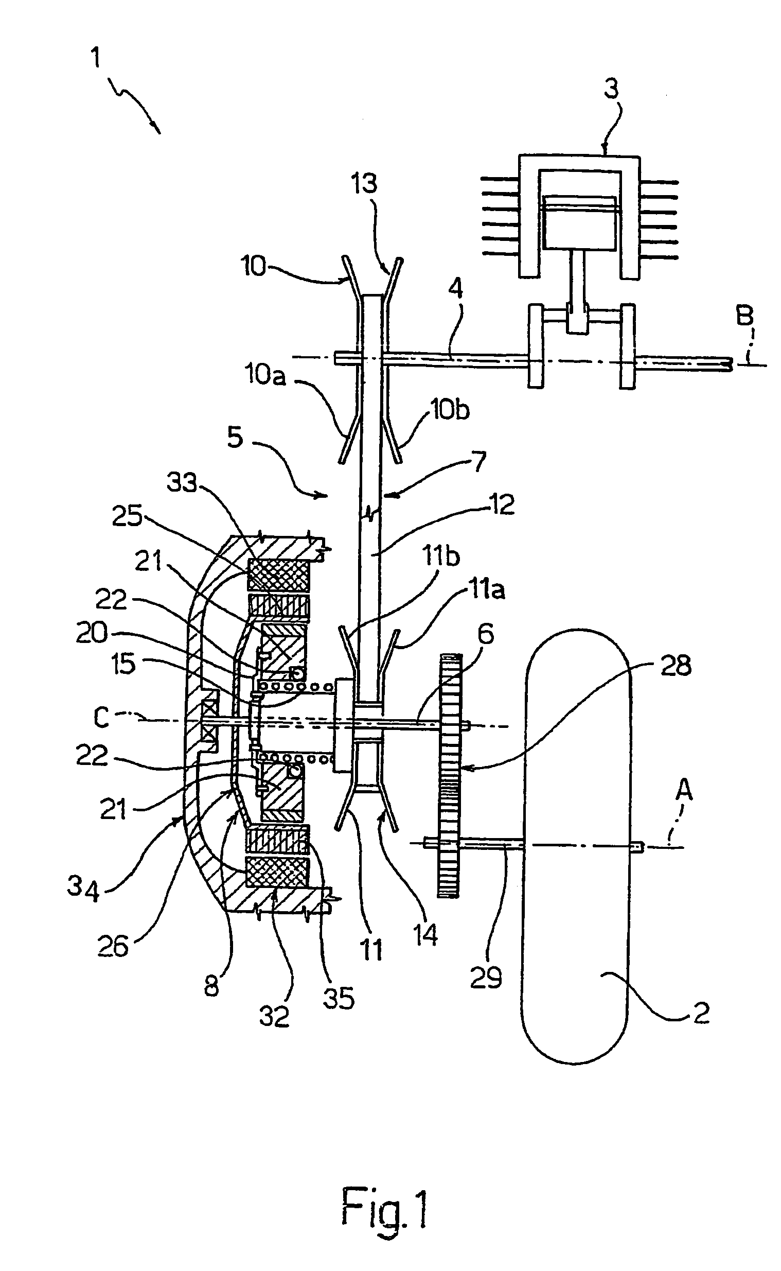
[0019]Number 1 in FIG. 1 indicates as a whole a hybrid drive assembly for a scooter having a rear drive wheel 2 of axis A.

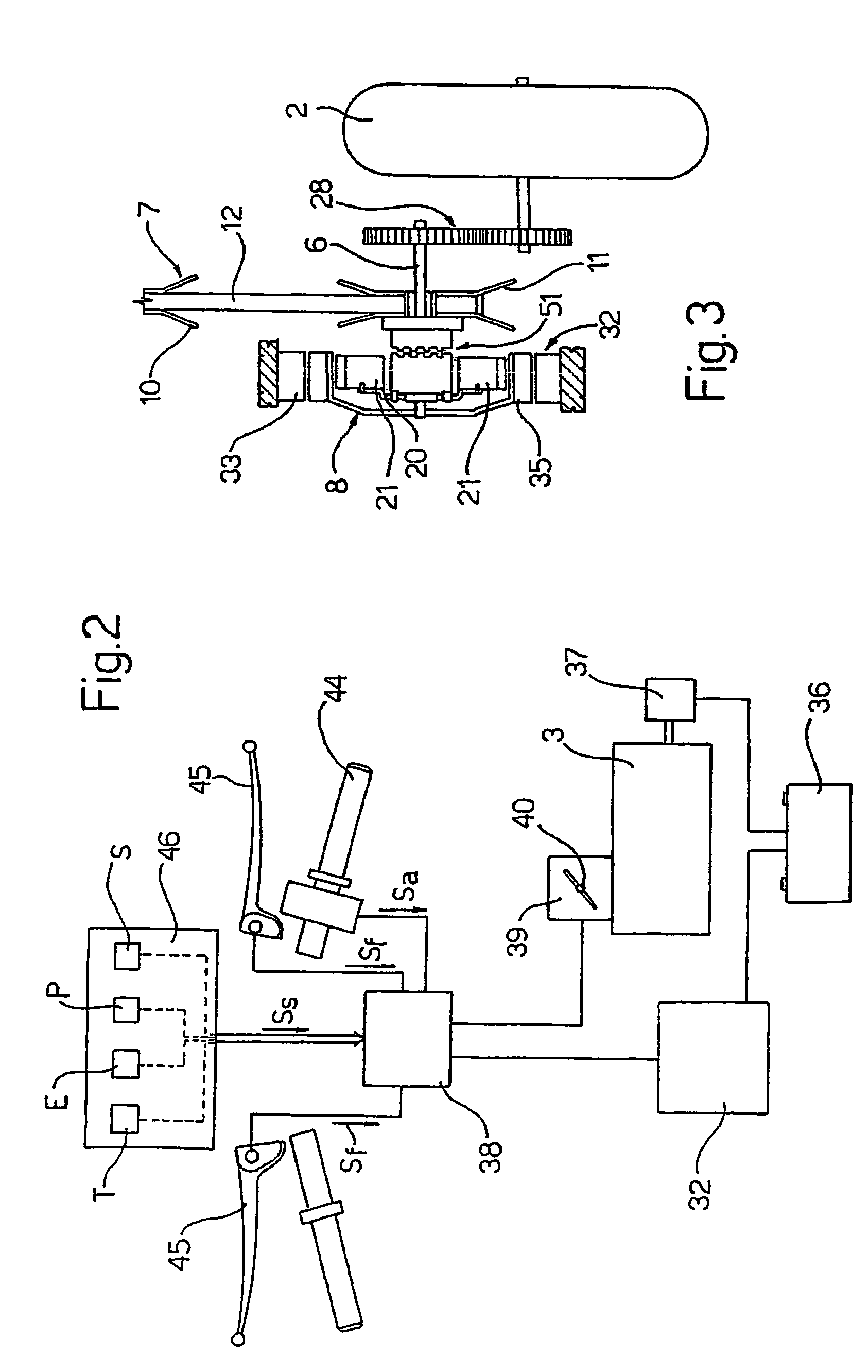
[0020]Drive assembly 1 comprises a combustion engine 3 having a drive shaft 4 of axis B parallel to axis A; and a transmission unit 5 interposed between drive shaft 4 and a propeller shaft 6 of axis C, parallel to axes A and B, and connected angularly to the drive wheel 2.

[0021]More specifically, transmission unit 5 comprises a continuously variable transmission or CVT 7 (hereinafter referred to simply as “CVT 7”), and a centrifugal clutch 8 in series with each other.

[0022]CVT 7 comprises a drive pulley 10 fitted to drive shaft 4; a driven pulley 11 coaxial with and fitted in angularly free manner to propeller shaft 6; and a V belt 12 looped about pulleys 10, 11. Pulleys 10, 11 have respective V grooves 13, 14 for belt 12, and are defined by two half-pulleys 10a, 10b and 11a, 11b respectively, which are movable axially with respect to each other to vary the width...


PUM


Abstract

A hybrid drive assembly (1) for a vehicle having at least one drive wheel (2), the drive assembly including an internal combustion engine (3); a transmission unit (5) interposed between a drive shaft (4) of the internal combustion engine (3) and a propeller shaft (6) connected angularly to the drive wheel (2), and in turn including a continuously variable transmission (7) having a drive pulley (10) connected angularly to the drive shaft (4) and a driven pulley (11), and a centrifugal clutch (8) having a hub (20) connected to the driven pulley, and a driven bell (26) connected to the propeller shaft (6); and an electric machine (32) having a rotor (35) integral with the bell (26) of the centrifugal clutch (8). The drive assembly (1) is controlled by a control unit (38), in response to a number of input signals (Ss, Sa, Sf), in a number of operating modes including an all-combustion propulsion mode, an all-electric propulsion mode, a first hybrid propulsion mode wherein the internal combustion engine (3) and the electric machine (32) are connected in series, and a second hybrid propulsion mode wherein the internal combustion engine (3) and the electric machine (32) are connected in parallel.

Description

TECHNICAL FIELD[0001]The present invention relates to a hybrid drive assembly for a road vehicle, in particular a scooter.BACKGROUND ART[0002]As is known, numerous road vehicle, in particular car, manufacturers are currently experimenting hybrid-propulsion vehicles, some of which have recently been marketed. Though “hybrid propulsion” normally refers to the use of two or more different propulsion systems, the solutions hitherto proposed are normally a combination of an internal combustion engine (hereinafter referred to simply as a “combustion engine”) and an electric motor, to exploit the advantages and compensate the disadvantages of each.[0003]More specifically, the main advantage of a combustion engine, and the reason why it is used almost exclusively in road vehicles, is the fuel distance obtainable by virtue of the high energy concentration of the fuel employed (substantially hydrocarbons). On the other hand, a combustion engine produces harmful emissions, can only operate wit...

Claims


Application Information

Patent Timeline
Patent Type & Authority Patents(United States)
IPC IPC(8): B60K1/00B60K6/20B60K6/38B60K6/48B60K6/543B62M7/12B62M23/02
CPCB60K6/38B60K6/48B60K6/543B62M7/12B60Y2200/126Y10T477/26Y02T10/6221Y10S903/903B62K2202/00B60L15/2054B60L2200/12B60L2240/507Y02T10/72B60L50/61B60L50/16Y02T10/62Y02T10/64Y02T10/7072Y02T10/70B62M23/02
Inventor VITALE, EMILIOFRENDO, FRANCESCOARNONE, LUIGIMARCACCI, MAURIZIORIGGIO, GIOVANNI
Owner UNIV DI PISA
Why Eureka
Try Eureka