Method and circuit for interpolating encoder output

a technology of encoder output and interpolation method, which is applied in the direction of transmission system, measurement device, instruments, etc., can solve the problems of synchronization errors, two-phase square wave frequency increase, and inability to use inexpensive transmission modes with transfer rates of around 10 to 40 mhz, so as to reduce synchronization errors and improve dynamic precision

Inactive Publication Date: 2008-04-01
MITUTOYO CORP
View PDF12 Cites 11 Cited by
  • Summary
  • Abstract
  • Description
  • Claims
  • Application Information

AI Technical Summary

Benefits of technology

[0019]The present invention is made to obviate above problems and object of this invention is to reduce synchronization errors between the external data request signal and the interpolation data for improved dynamic precision.
[0029]According to the present invention, it is possible to make interpolations with a high degree of accuracy without impairing the dynamic precision even if A / D conversion requiring a long conversion time or processing requiring a long operation time is involved. This facilitates cost saving and miniaturization.
[0030]Moreover, the data at the point in time when the data request signal is input can be delayed accurately for latch or interpolation operation. This makes it possible to maintain high precision and high resolution without increasing the operation time.

Problems solved by technology

Because of limited operation time for A / D conversion and signal correction, this method requires discrete sampling for the A / D conversion.
If the sampling time is long, it is impossible to establish precise synchronization with external trigger signals (data request signals) such as an origin signal and a servo control signal, thereby causing a shift in position.
There are problems, however, because (1) the enhanced number of interpolations increase the two-phase square waves in weight, so that the two-phase square waves become higher in frequency even at the same feed speed.
This makes it impossible to use inexpensive transmission modes having transfer rates of around 10 to 40 MHz, such as RS422 and RS485.
Data transmission over a distance as long as several tens of meters in a parallel fashion may increase the cost and power consumption due to the large number of cable conductors.
On the other hand, the ADC sampling period Pck1 is also limited.
Furthermore, the use of the ADC circuit having a greater number of bits for high resolution has also produced the problem of increased operation time.

Method used


Image

  • Method and circuit for interpolating encoder output
  • Method and circuit for interpolating encoder output
  • Method and circuit for interpolating encoder output

Examples


Embodiment Construction

[0045]Hereinafter, exemplary embodiments of the present invention will be described in detail with reference to the drawings.

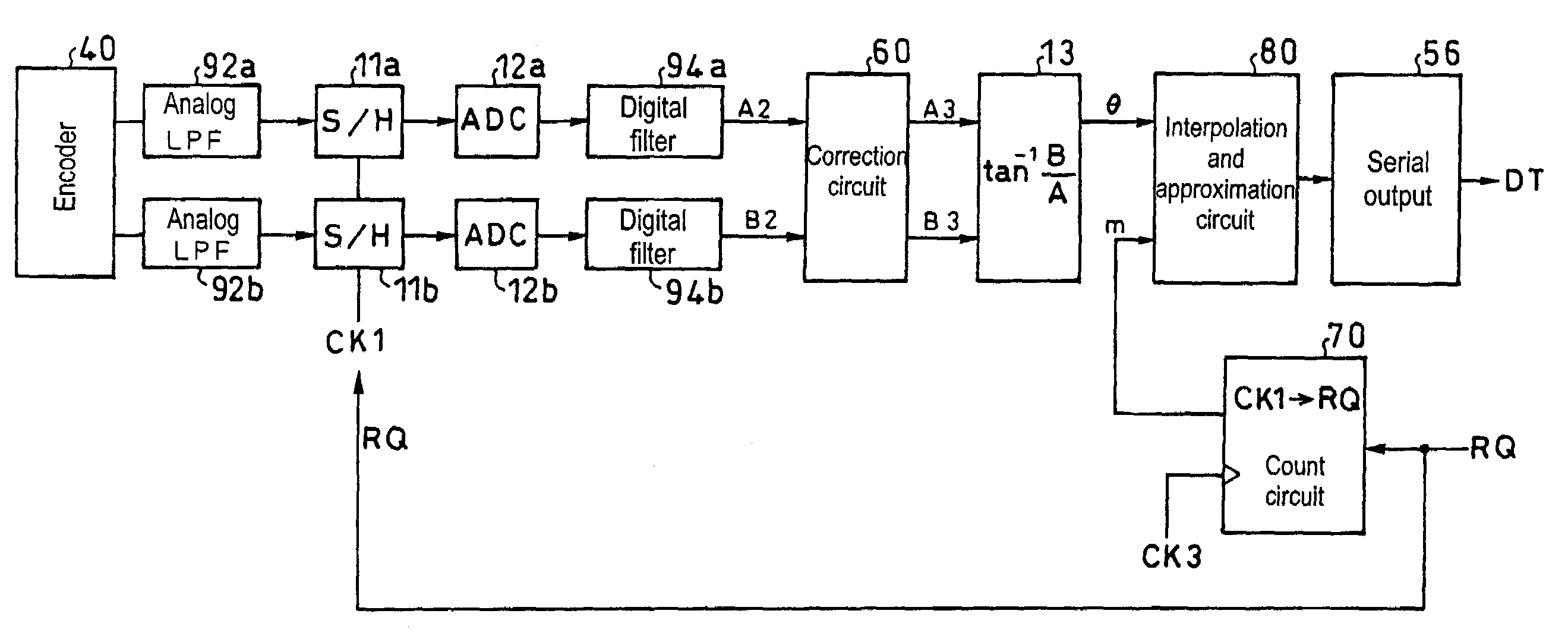
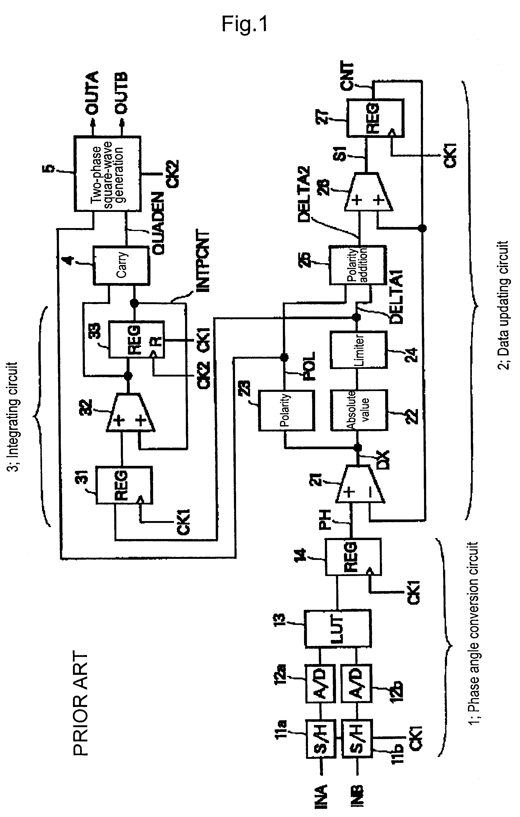
[0046]As shown in FIG. 5, a first exemplary embodiment of the present invention is an encoder apparatus which comprises, as in the conventional example shown in FIGS. 1 and 3: an encoder 40; S / H circuits 11a and 11b; ADC circuits 12a and 12b; a LUT memory 13; a two-phase square-wave uniform pulse generating circuit 6 which corresponds to the data updating circuit 2, the integrating circuit 3, the carry detection circuit 4, and the two-phase square wave generating circuit 5; a direction discrimination up / down counter 52; and a latch circuit 54. A correction circuit 60 for making the same offset and amplitude-ratio adjustment as in patent document 3 is interposed between the ADCs 12a and 12b and the LUT 13.

[0047]While two-phase square waves are typically used to transmit data, high-frequency transmission is difficult as described in the foregoing problems. In th...


PUM


Abstract

Two-phase sinusoidal signals QA, QB output from an encoder are interpolated by sample-and-hold (S / H) circuits and A / D conversion (ADC) circuits, and data D is output in accordance with a data request signal RQ from exterior. For this interpolation of encoder output, a direction discrimination up / down counter is arranged near a two-phase square-wave uniform pulse generating circuit, and the data D is latched and output using a signal which is obtained by delaying the data request signal RQ. This can reduce synchronization errors between the data request signal RQ from exterior and the interpolated data, with an improvement in dynamic precision.

Description

CROSS-REFERENCE TO RELATED APPLICATION[0001]The disclosure of Japanese Patent Application No. 2005-233558 filed Aug. 11, 2005 including specification, drawings and claims is incorporated herein by references in its entirety.BACKGROUND OF THE INVENTION[0002]1. Field of the Invention[0003]The present invention relates to a method and a circuit for interpolating an encoder output. In particular, the invention relates to a method and a circuit for interpolating an encoder output, by which two-phase sinusoidal signals output from an encoder are interpolated through sample-and-hold and A / D conversion, thereby outputting data in accordance with a data request signal from exterior, suited to encoder (photoelectric type, magnetic type, electromagnetic induction type, capacitance type, etc.) outputting two-phase sinusoidal signals having a phase difference of 90° and laser length measuring machines.[0004]2. Description of the Related Art[0005]Encoders have working limits on the pitches of the...

Claims


Application Information

Patent Timeline
Patent Type & Authority Patents(United States)
IPC IPC(8): H03M1/48
CPCG01D5/24404H03M1/207H03M1/303
Inventor KIRIYAMA, TETSUROKOISO, RYUICHIYOSHINAKA, TOSHIROU
Owner MITUTOYO CORP
Why Eureka
Try Eureka