
Anchoring member to facilitate fastening daughter boards to a mother board and a method for use

a technology of an anchoring member and a mother board, which is applied in the direction of printed circuit aspects, support structure mounting, electrical apparatus construction details, etc., can solve the problems of increasing the amount of area, area or real estate on the mother board used by the structural element, and the inability to use other elements or purposes

Active Publication Date: 2008-04-01
SIEMENS CANADA LTD
View PDF17 Cites 88 Cited by
  • Summary
  • Abstract
  • Description
  • Claims
  • Application Information

AI Technical Summary

Benefits of technology

[0012]Accordingly, one advantage of at least one aspect of the present invention is that the a single anchoring member can be used to secure daughter boards to either side of a mother board and in parallel arrangement thereto. This can decrease the real estate used on the mother board because a single structural element can be used to secure two different daughter boards to the same mother board. This can also decrease the complexity of the overall circuit on the mother board by decreasing the number of apertures that must be incorporated into the mother board for securing the daughter boards thereto.
[0013]A further advantage of at least one aspect of the present invention is that the cost of manufacture can be decreased in that a single structural element can be used to secure two daughter boards, thereby decreasing the assembly costs as well as the material costs.
[0014]A further advantage of at least one aspect of the present invention is that the design of the daughter boards can be made more symmetrical, particularly where the daughter boards perform the same function. In this way, a single aperture, or other fastening device, can be used on a daughter board rather than having separate apertures or fastening devices in different locations on the daughter board corresponding to the different possible locations a corresponding structural element on a mother board could fasten to a daughter board depending on the orientation of the daughter board. Similarly, if the same structural element is also to be used for a heat sink, such as an aluminium plate, a single offsetting hole or other fastening element can be used to fasten the heat sink to the structural element on the mother board regardless of the orientation of the aluminium board with respect to the mother board during manufacture.

Problems solved by technology

In particular, prior art devices have generally been one sided, meaning that each structural device can only secure a daughter board to one side of a mother board.
Clearly, this can increase the cost because of the number of structural elements required to secure the daughter boards to the mother boards.
Furthermore, this can greatly increase the amount of area, also referred to as “real estate”, used on the mother board because, whether or not a structural element is used to secure a mother board to one side or the other side of the mother board, the area or real estate on the mother board used by the structural element is gone and cannot be used for other elements or purposes.
Furthermore, the additional elements present on a mother board increase the complexity of the wiring circuit printed on the mother board thereby increasing the overall cost to design and build a mother board.
This also decreases the available area or real estate available for use on the daughter board.
This also increases the complexity of the wiring circuit printed on the daughter board.

Method used


Image

  • Anchoring member to facilitate fastening daughter boards to a mother board and a method for use
  • Anchoring member to facilitate fastening daughter boards to a mother board and a method for use
  • Anchoring member to facilitate fastening daughter boards to a mother board and a method for use

Examples


Embodiment Construction

[0025]Preferred embodiments of the invention and its advantages can be understood by referring to the present drawings. In the present drawings, like numerals are used for like and corresponding parts of the accompanying drawings.

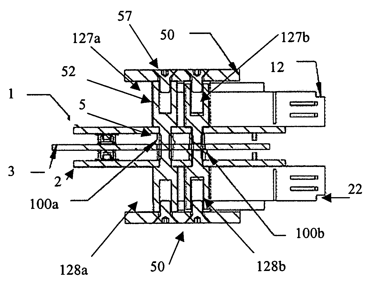
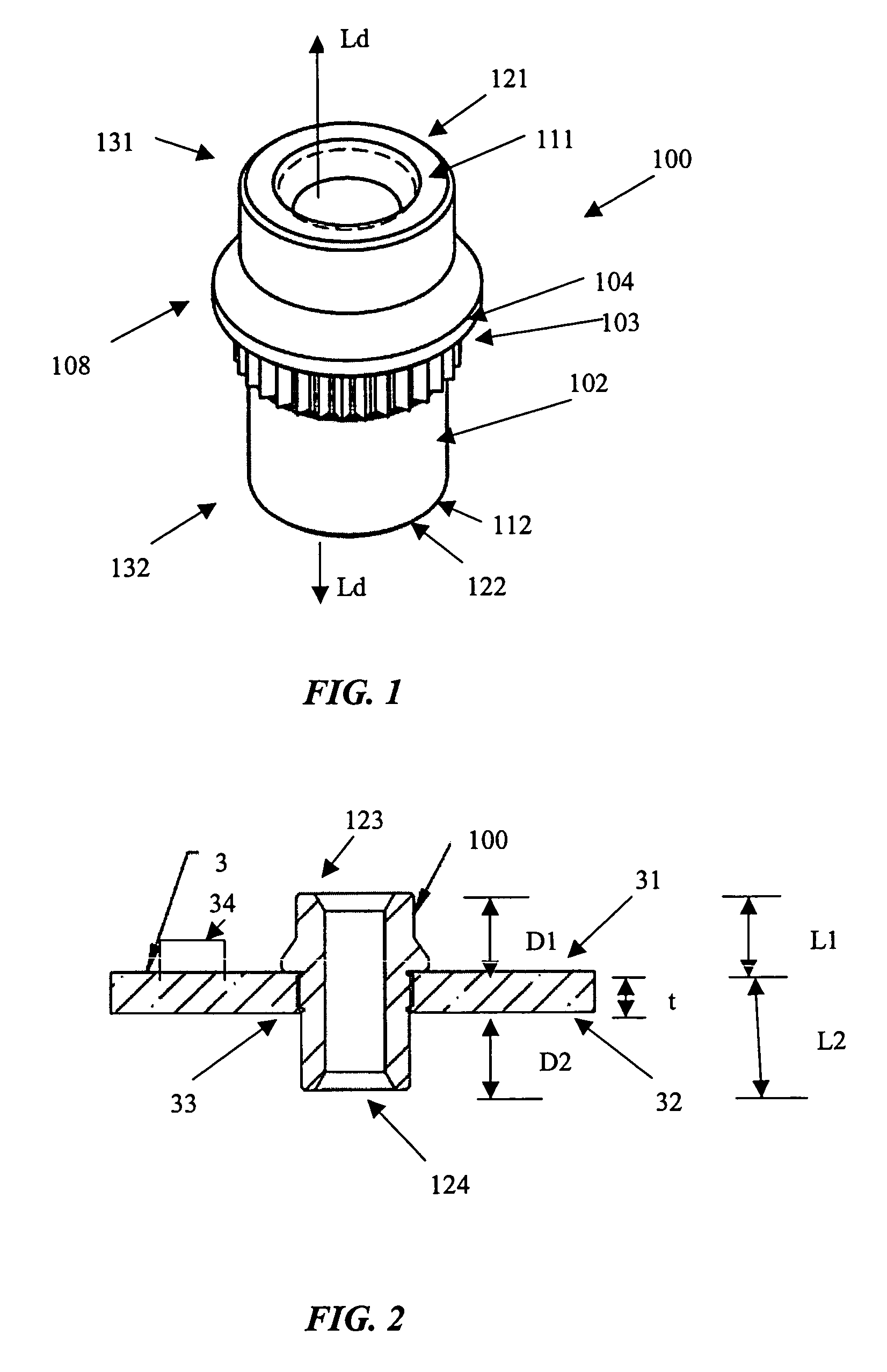
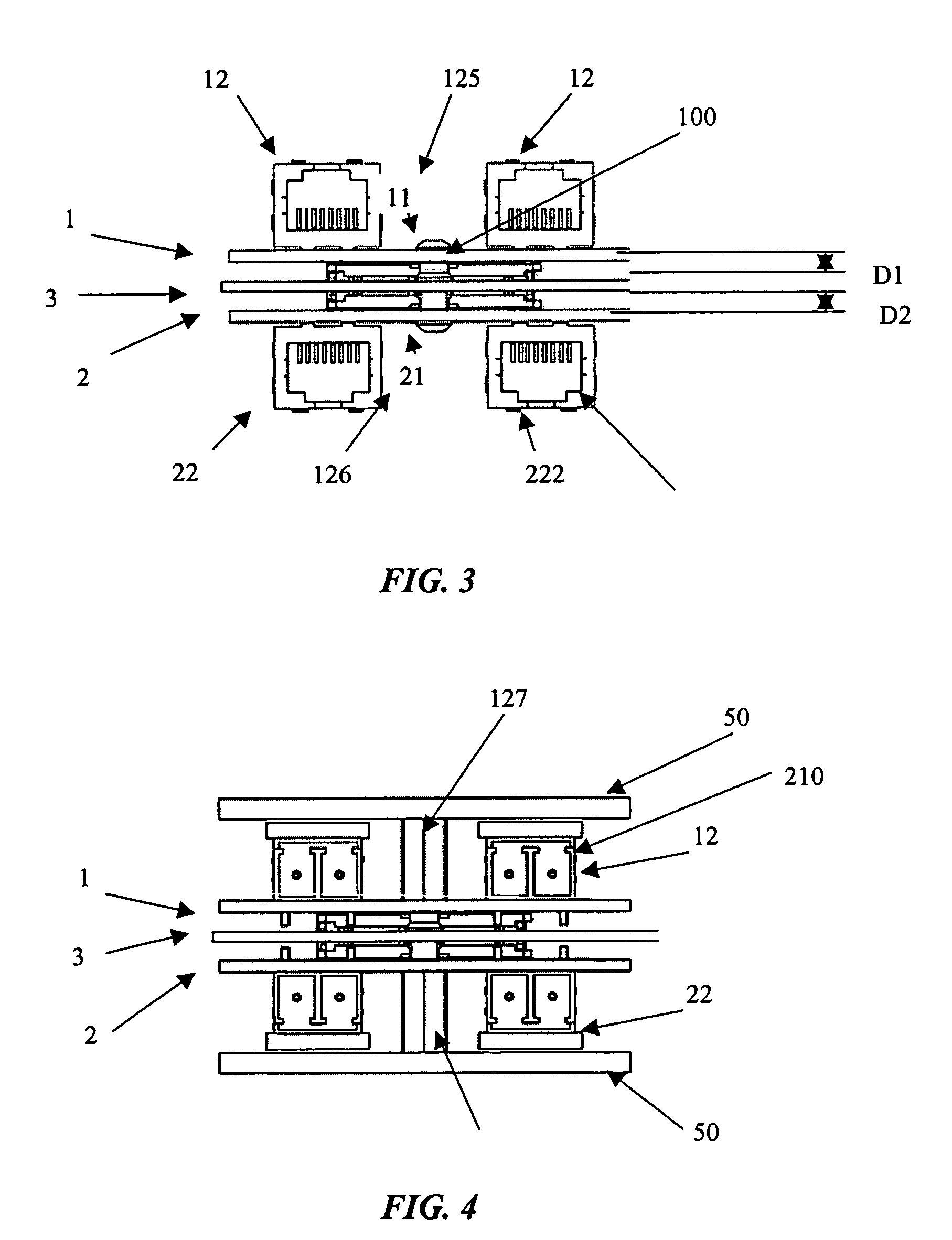
[0026]As shown in FIG. 1, one embodiment of the present invention relates to a structural element and, in particular, an anchoring member, shown generally by reference numeral 100, for facilitating fastening a first daughter board 1 and a second daughter board 2 in parallel arrangement on either side of a mother board 3. The anchoring member 100 comprises, in one preferred embodiment, an elongated body 102 extending in a longitudinal direction, indicated generally by the arrow identified with the symbol Ld.

[0027]Preferably, the anchoring member 100 comprises a friction fit surface, as shown generally by reference numeral 103, for securing the elongated body 102 to the mother board 3. The friction fit surface 103 can be any type of surface which can secure t...


PUM


Abstract

An anchoring member and related method are disclosed for substantially parallel assembly of two additional daughter printed circuit boards (PCB) and heat sink on each side of main of mother PCB, and to retain a predetermined mating distance thereto to retain a predetermined mating distance thereto. The anchoring member comprises an elongated body extending in a longitudinal direction and having a first coupling member on one end for coupling the first daughter board in a substantially perpendicular orientation to the longitudinal direction on a first side of the mother board. The elongated body also comprises a second coupling member at the opposite end from the elongated body from the first coupling member for coupling the second daughter board in a substantially perpendicular orientation to the longitudinal direction on a second side of the mother board. The elongated body also has a positioning flange for positioning the elongated body in an aperture of the mother board at an inserted position and a friction fit surface for interacting with the aperture of the mother board to secure the elongated body in the inserted position.

Description

CROSS REFERENCE TO RELATED APPLICATION[0001]This application claims priority to and the benefit of Canadian Application No. 2.552,620, filed on Jul. 20, 2006.FIELD OF THE INVENTION[0002]The present invention relates to the field of printed circuit boards (“PCB”). More particularly, the present invention relates to devices and methods for fastening daughter boards in parallel relation to mother boards a predetermined distance apart.BACKGROUND OF THE INVENTION[0003]In the past, there have been many different types of PCBs. Furthermore, the PCBs can be arranged and connected together in arrangements, sometimes referred to as mother board and daughter board arrangements. Typically, a mother board is a main PCB and a daughter board is a peripheral or secondary PCB, usually smaller in size than the mother board and physically and electrically connected thereto.[0004]Typically, a daughter board is arranged in a perpendicular fashion to the mother board. However, a daughter board can also b...

Claims


Application Information

Patent Timeline
Patent Type & Authority Patents(United States)
IPC IPC(8): H05K7/02
CPCH05K1/141H05K7/142H05K3/301H05K2203/1572H05K2201/1059H05K2201/10598H05K2201/2036H05K2201/042
Inventor ZENG, GUANGMOORE, ROGERDIAS, CLIVE
Owner SIEMENS CANADA LTD
Learn More