Laser alignment device

a laser alignment and laser technology, applied in the direction of reference lines/planes/sectors, instruments, transportation and packaging, etc., can solve the problem of limiting the use of laser alignment devices, and achieve the effects of convenient operation, simple structure and economical utility

Inactive Publication Date: 2008-04-01
NANJING CHERVON IND
View PDF2 Cites 17 Cited by
  • Summary
  • Abstract
  • Description
  • Claims
  • Application Information

AI Technical Summary

Benefits of technology

[0006]The present invention is intended to provide a laser alignment device which has a simple structure, easy operation and economical utility, and which may form not only a horizontal planar laser beam, but also a vertical planar laser beam.
[0008]The laser alignment device of the present invention may be settled to a settling surface through two different surfaces, that is, the first surface and the second surface, so as to project not only a horizontal planar laser beam but also a vertical planar laser beam without an additional laser emitting unit, and thereby to extend the use range for the same laser alignment device. Furthermore, the laser alignment device of the present invention may sense automatically the deviating degree from the horizontal or vertical for the planar laser beam, so as to omit the step of adjusting the device manually which simplifies its operation.
[0009]In one preferred embodiment of the present invention, the first mounting plane is perpendicular to said second mounting plane. Using this structure, it is easy to fix the first and the second obliquity sensing units perpendicular to each other.

Problems solved by technology

However, the laser alignment devices of the above patents can only form a laser line on a target surface in a fixed direction such as a vertical surface, which limits the use of laser alignment devices.

Method used


Image

  • Laser alignment device
  • Laser alignment device
  • Laser alignment device

Examples


Embodiment Construction

[0017]While this invention is susceptible of embodiments in many different forms, there is shown in the drawings and will herein be described in detail preferred embodiments of the invention with the understanding that the present disclosure is to be considered as an exemplification of the principles of the invention and is not intended to limit the broad aspect of the invention to the embodiments illustrated.

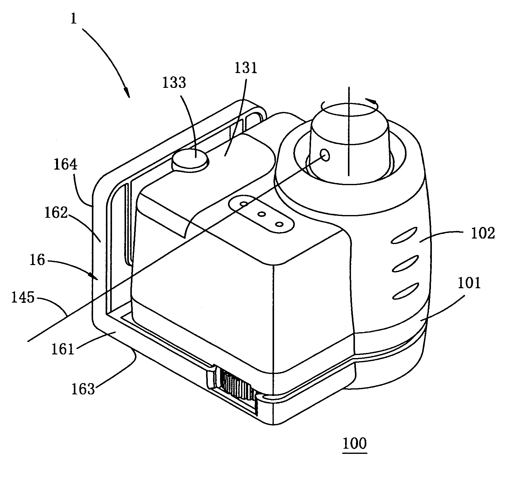
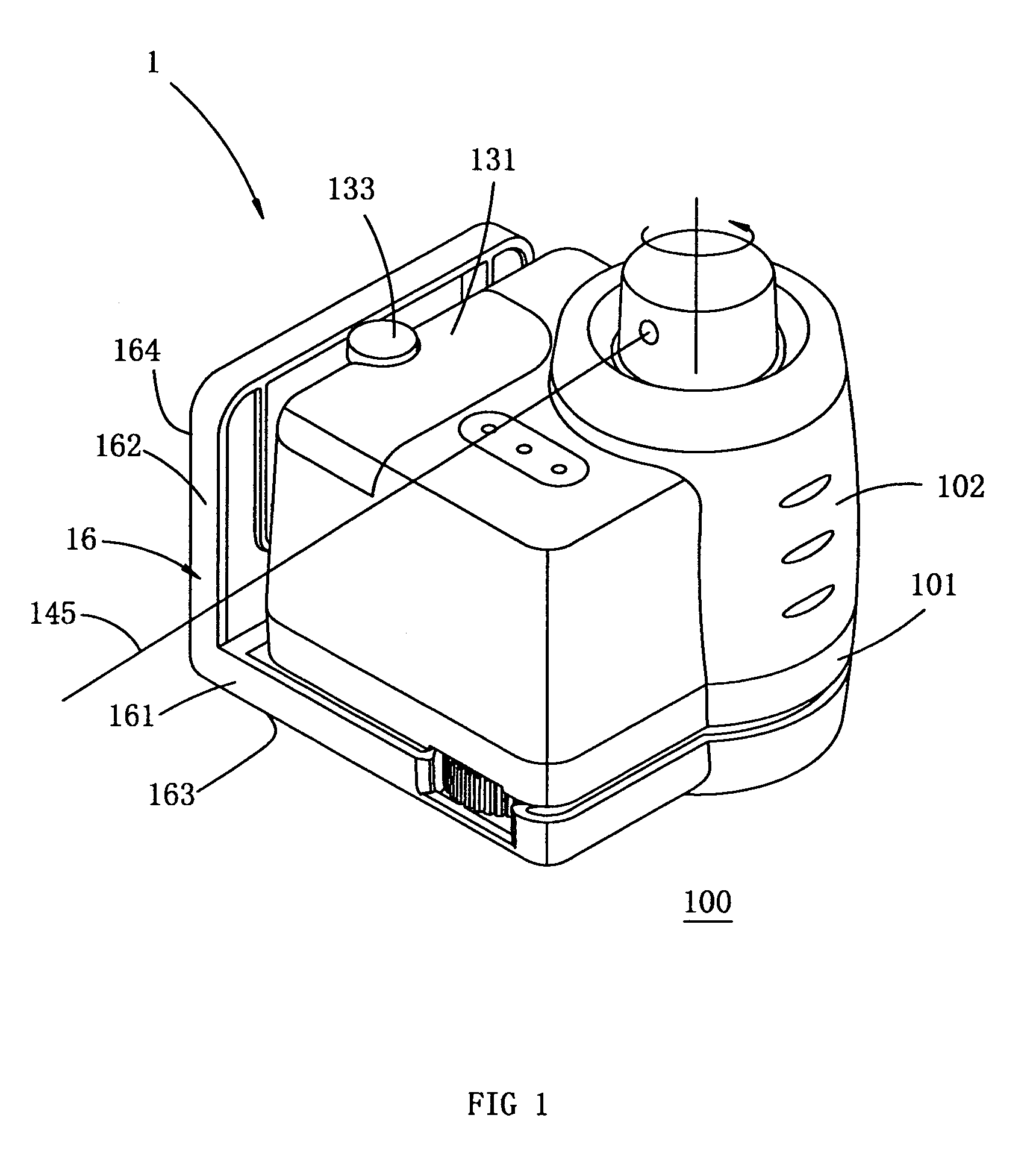
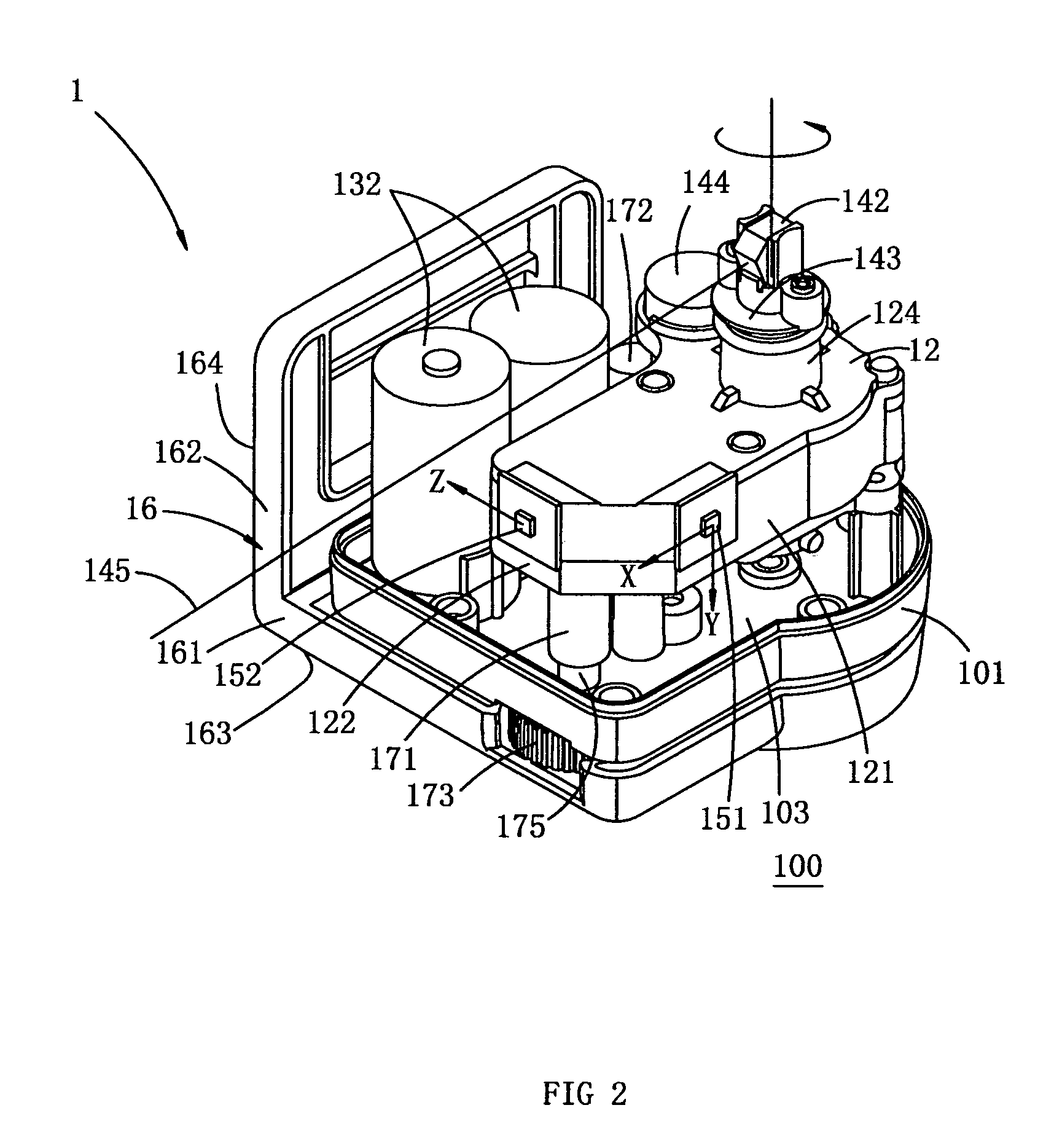
[0018]FIGS. 1-3 show a laser alignment device 1 of one preferred embodiment according to the present invention.

[0019]In one preferred embodiment, the laser alignment device 1 includes a bracket 16 and a casing composed of an upper casing 102 and a lower casing 101. A laser mounting frame 12 is provided in the casing. A laser emitting unit is fixed on the laser mounting frame 12. The bracket 16 includes a first support portion 161 and a second support portion 162 both of which are perpendicular to each other.

[0020]The two support portions 161 and 162 of the bracket 16 have outsi...


PUM


Abstract

The present invention discloses a laser alignment device which has a simple structure, easy operation and economical utility, and which includes a casing, a laser emitting unit that is mounted in the casing and may emit a planar laser beam, a first mounting plane and a second mounting plane connected fixedly to the laser emitting unit, a first and a second electronic obliquity sensing units fixed on the first and the second mounting planes respectively, an automatic adjusting means, a first and a second surfaces both of which may contact with the settling surface of the laser alignment device, said first surface being connected moveably with said laser emitting unit through said automatic adjusting means, and a control circuit connected electrically with said first and second obliquity sensing units and said automatic adjusting means, at least the first one of said first and second obliquity sensing units being a double shaft obliquity sensing unit. Using this configuration, the same laser alignment device may form not only a horizontal planar laser beam but also a vertical planar laser beam, and may sense automatically the deviating degree from the horizontal or vertical for the planar laser beam adjust it automatically, so as to omit the step of adjusting manually and simplify its operation.

Description

CROSS-REFERENCE TO RELATED APPLICATIONS[0001]This application claims priority to Chinese Application No. 200520074523.7 filed Aug. 16, 2005, the entire disclosure of which is incorporated herein by reference. Priority to this application is claimed under 35 U.S.C. 119, 120 and / or 365.TECHNICAL FIELD[0002]The invention relates to a laser alignment device, and more particularly, to a laser alignment device that can emit a planar laser beam to a target surface to form a laser line as a reference line for other operation.BACKGROUND OF THE INVENTION[0003]Currently, laser alignment devices are widely used in fields such as building engineering, home decorating and the like. U.S. Pat. No. 4,031,629 issued to Paluck on Jun. 28, 1977, discloses a laser alignment device in which a motor drives a laser beam to rotate to form a planar laser beam, thereby forming a straight laser line onto a target surface. The main body of the '629 patent is adjusted manually to horizontal, with the indication ...

Claims


Application Information

Patent Timeline
Patent Type & Authority Patents(United States)
IPC IPC(8): G01C15/00B64C17/02G01C5/00G02B6/00G01B11/26
CPCG01C15/004G01C15/008
Inventor YANG, DEZHONG
Owner NANJING CHERVON IND
Why Eureka
Try Eureka