Optical recording medium and its manufacturing method

a technology of optical recording medium and manufacturing method, which is applied in the direction of flat record carrier container, record information storage, instruments, etc., can solve the problems of insufficient freedom of duty ratio change, difficult to record or reproduce record marks from both lands and grooves with a high c/n ratio, etc., to achieve the effect of increasing the design freedom necessary for improving the signal property and changing the signal property

Inactive Publication Date: 2008-04-01
SONY CORP
View PDF17 Cites 6 Cited by
  • Summary
  • Abstract
  • Description
  • Claims
  • Application Information

AI Technical Summary

Benefits of technology

[0030]To obtain good signals, maintain the optical contrast in a good condition and prevent thermal diffusion while preventing the recording layer from becoming discontinuous islands, thickness of the recording layer is typically adjusted in the range not thinner than 5 nm and not thicker than 50 nm, or more preferably, in the range not thinner than 10 nm and not thicker than 40 nm.
[0040]According to the invention having the above-summarized configuration, since the thickness a of the record-assist layer is controlled to be larger than ¼ of the thickness d of the recording layer and smaller than three times of the thickness d, signal property can be changed by not only by changing the size of the concavo-convex but also by modifying the thickness of the record-assist layer. Therefore, design freedom necessary for improvement of the signal property can be increased.

Problems solved by technology

However, such optical discs employing the land / groove recording suffer a difference of the thermal property exerted to the recording layer because of the difference in physical configuration between lands and grooves when recording laser beams are irradiated to lands and grooves respectively.
Therefore, vector diffraction of light causes uneven distribution of irradiated laser beams between lands and grooves, and it has been difficult to record or reproduce record marks from both lands and grooves with a high C / N ratio (carrier-to-noise ratio).
However, only change of the duty ratio cannot bring about ample freedom.
This condition digresses the optimum condition for deposition of the recording layer and invites deterioration of signal characteristics of the recording layer.

Method used


Image

  • Optical recording medium and its manufacturing method
  • Optical recording medium and its manufacturing method
  • Optical recording medium and its manufacturing method

Examples


first embodiment

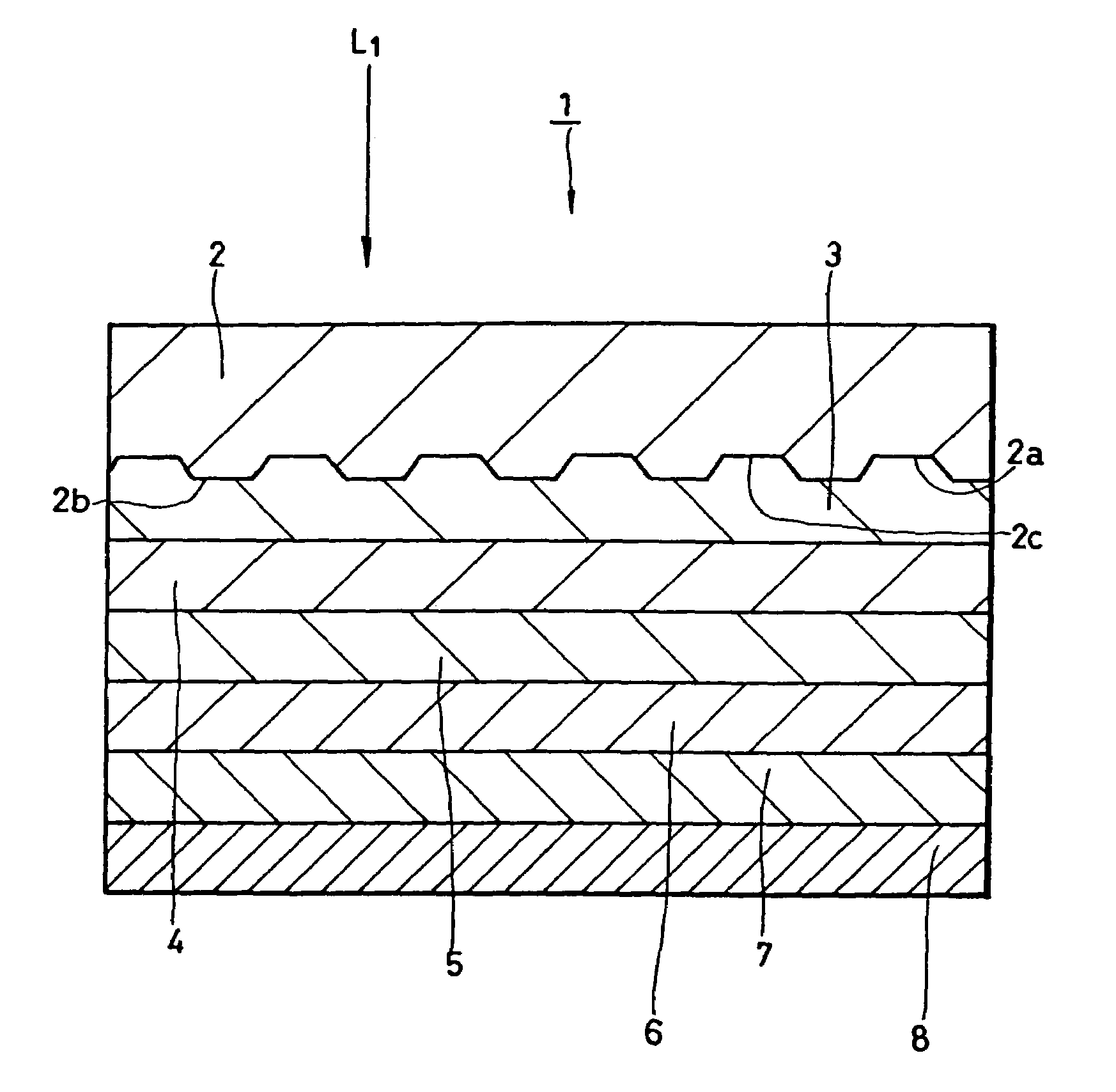
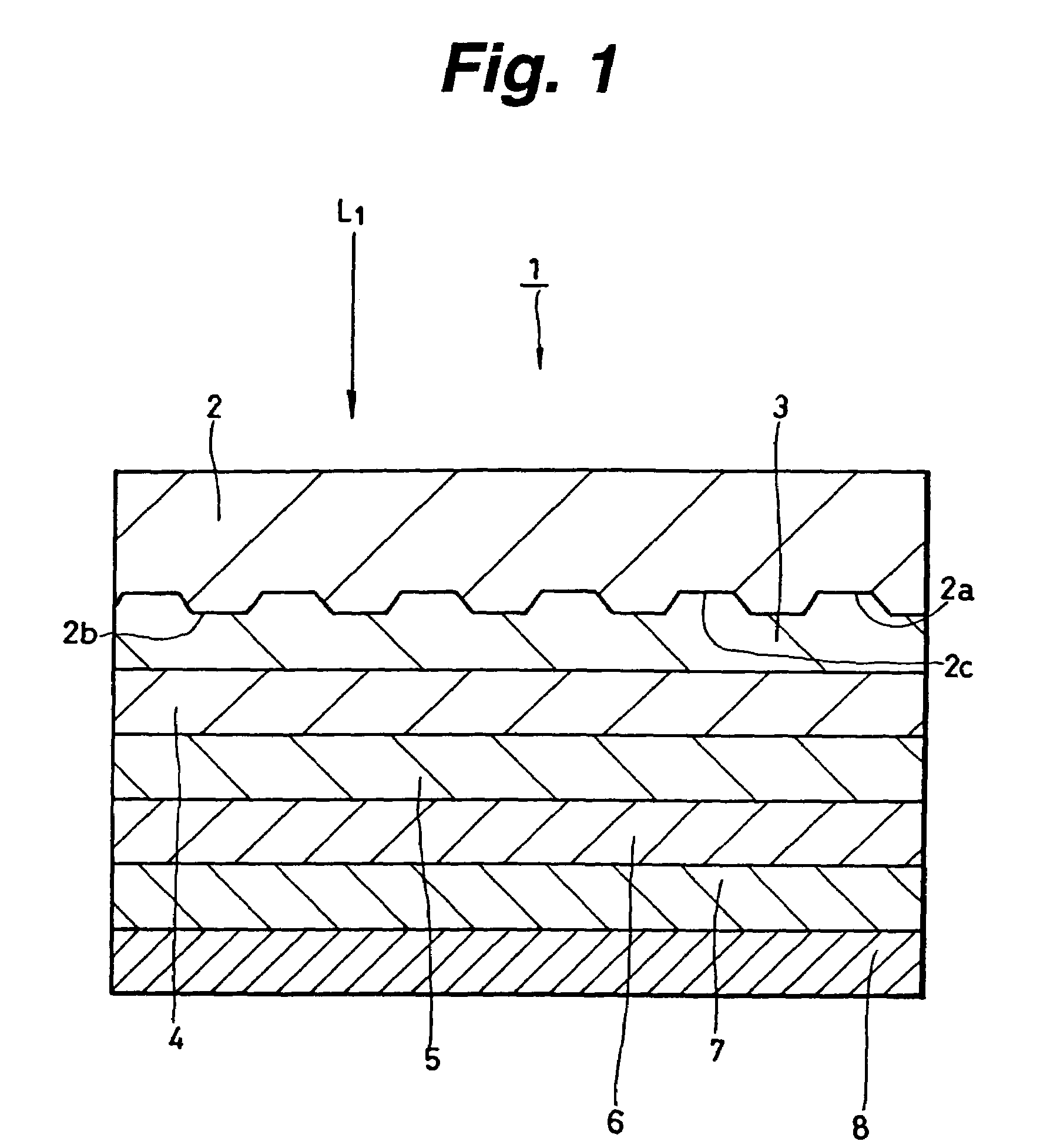
[0051]As shown in FIG. 1, the optical disc 1 includes a multi-layered film made of a first dielectric layer 3, recording layer 4, record-assist layer 5, second dielectric layer 6 and first reflection layer 7 that are stacked on one major surface 2a of a disc substrate 2, and an ultraviolet-curing resin layer 8 formed to cover the multi-layered film.

[0052]The disc substrate 2 is made of a material that can transmit at least a laser beam used for recording and reproducing information signals. Examples of materials usable for forming the disc substrate 2 are plastic materials such as polycarbonate-family resins, polyolefin resin and acrylic-family resins, and glass. Among these materials, plastic materials are preferable from the economical viewpoint. In the first embodiment, the disc substrate 2 is made of, for example, polycarbonate (PC). The disc substrate 2 is sized 130 mm in diameter and approximately 1.2 mm in thickness, for example.

[0053]The major surface 2a of the disc substra...

second embodiment

[0083]As shown in FIG. 5, the optical disc 11 includes a multi-layered film made of a second reflection layer 13, third dielectric layer 14, record-assist layer 15, recording layer 16 and fourth dielectric layer 17 sequentially stacked on one major surface 12a of a disc substrate 12, and a light-transmitting layer 18 formed to cover the multi-layered film.

[0084]The disc substrate 12 is made of a low water-absorbing material such as polycarbonate (PC) or cycloolefin polymer (such as Zeonex (registered trademark)). Thickness of the disc substrate 12 is, for example, in the range from 0.6 to 1.2 mm. In the second embodiment, it is 1.1 mm thick, for example. Diameter of the disc substrate 12 is 120 mm for example. The optical disc according to the second embodiment is configured to record / reproduce information signals when a laser beam is irradiated to he disc substrate 12 from one side thereof where the thin light-transmitting layer 18 exists. Therefore, the disc substrate 12 can be s...


PUM

PropertyMeasurementUnit
thicknessaaaaaaaaaa
thicknessaaaaaaaaaa
thicknessaaaaaaaaaa

Abstract

A multi-layered film made of sequentially stacked first dielectric layer, recording layer, record-assist layer, second dielectric layer and first reflection layer on a disc substrate having a concavo-convex structure at least on one surface thereof. An ultraviolet-setting resin layer is formed to cover the multi-layered film. The record-assist layer is controlled in thickness to satisfy the relation d / 4<a<3d, or more preferably the relation d / 2≦a≦2d, between the thickness d of the recording layer and the thickness a of the record-assist layer. The stacking order of the multi-layered film may be opposite. In this case, a light-transmitting sheet is provided to cover the multi-layered film via a bonding layer.

Description

TECHNICAL FIELD[0001]This invention relates to an optical recording medium and its manufacturing method especially suitable for application to an optical recording medium employing a land / groove recording technique.BACKGROUND OF THE INVENTION[0002]Recently, along with enhancement of recording density of optical recording mediums such as optical discs, development of the technique of effectively using the area on the recording surface of an optical disc has been pushed forward to enhance the recording density.[0003]The recording surface of any disc substrate has concavo-convex called lands and grooves respectively. In conventional optical discs, only lands or only grooves were used to record recording marks. However, with the need of enhancing the recording density of optical discs, a technique for recording record marks on both lands and grooves, i.e. a land / groove recording technique, has been brought into use as a format of optical discs. An example of optical discs combined with ...

Claims


Application Information

Patent Timeline
Patent Type & Authority Patents(United States)
IPC IPC(8): G11B23/03G11B7/007G11B7/2403G11B7/24035G11B7/24073G11B7/24079G11B7/24085G11B7/24091G11B7/243G11B7/2433G11B7/2437G11B7/2542G11B7/257G11B7/2578G11B7/26
CPCG11B7/2403G11B7/24067G11B7/243G11B7/257G11B7/00718G11B7/24079G11B7/2542G11B7/2578G11B2007/24312G11B2007/24314G11B2007/24316G11B2007/25708G11B2007/2571G11B2007/25713
Inventor HAYASHIBE, KAZUYAOHWADA, KATSUYA
Owner SONY CORP
Why Eureka
Try Eureka