Hydraulic pressure supply control in industrial vehicle

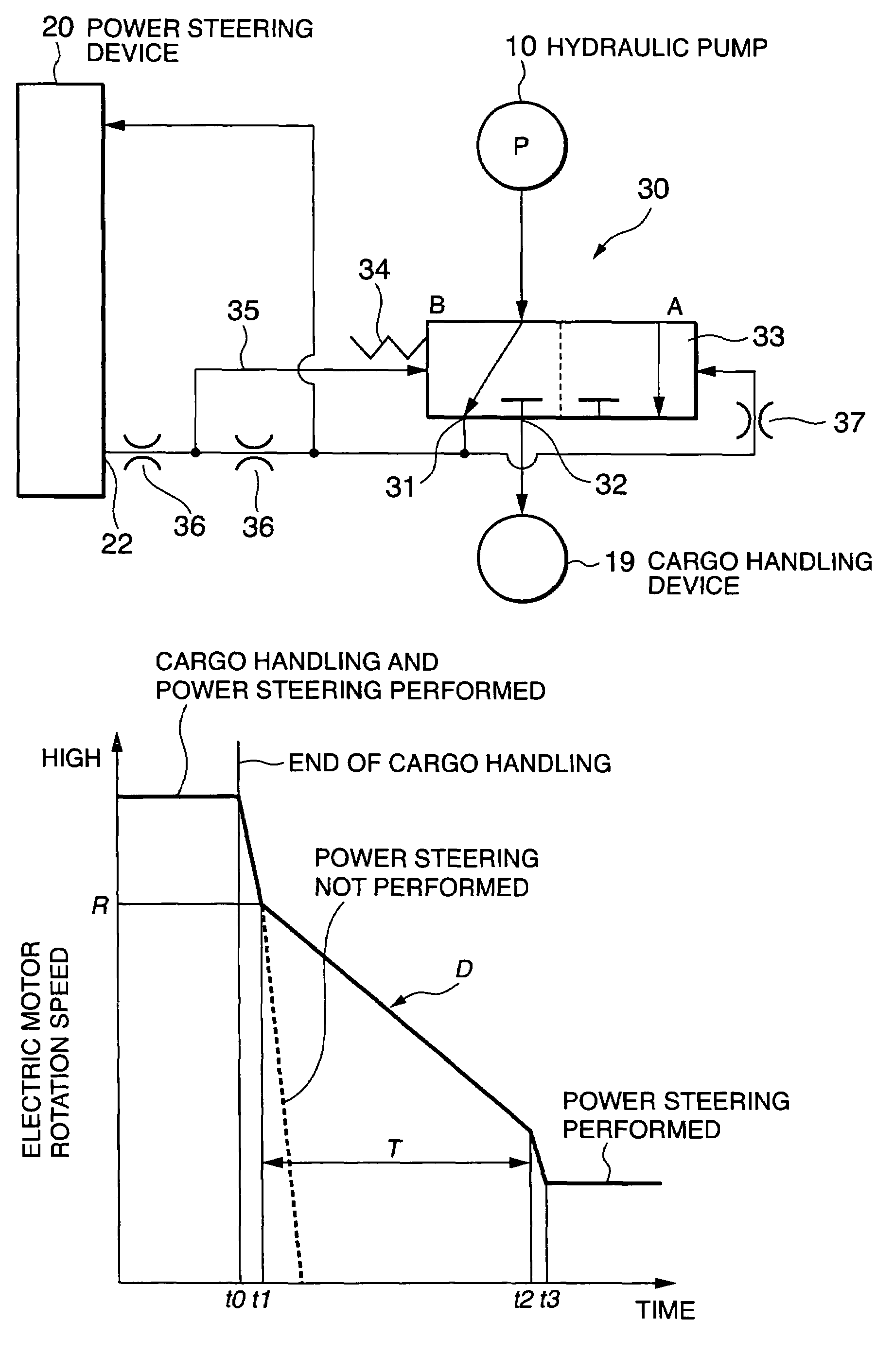
a technology for industrial vehicles and hydraulic pressure, applied in the direction of fluid couplings, couplings, transportation and packaging, etc., can solve the problems of time delay, short supply of working oil for the power steering device, and a temporary short supply of working oil, so as to achieve the effect of reducing the amount of working oil supplied to the power steering devi

Active Publication Date: 2008-04-08
NISSAN FORKLIFT CO LTD
View PDF5 Cites 2 Cited by
  • Summary
  • Abstract
  • Description
  • Claims
  • Application Information

AI Technical Summary

Benefits of technology

[0006]Specifically, when the operation of the cargo handling device stops in a state where both the power steering device and the cargo handling device are in operation, the controller lowers the rotation speed of the electric motor so as to decrease the discharge flow rate of the hydraulic pump. On the other hand, the priority flow rate control valve displaces the valve spool so as to increase the distribution ratio of the pressurized working oil to the power steering device.
[0008]It is therefore an object of this invention to prevent a kickback from occurring when a hydraulic device stops operation in a state where the hydraulic pump supplies pressurized working oil to both the power steering device and the hydraulic device.
[0013]The method comprises causing a discharge flow rate of the hydraulic pump to increase when the cargo handling device is in operation and decrease when the cargo handling device stops operation, determining if the cargo handling device has stopped operation in a state where both the power steering device and the cargo handling device are in operation, and causing a delay in decreasing the discharge flow rate of the hydraulic pump when the cargo handling device has stopped operation in a state where both the power steering device and the cargo handling device are in operation.

Problems solved by technology

Herein, reduction in the flow area caused by the orifice brings about a time delay extending from a variation in the load signal pressure in the power steering device until displacement of the valve spool occurs.
This time delay may cause the following problem.
However, if the discharge flow rate of the hydraulic pump is decreased before the completion of displacement of the valve spool due to the above time delay, the working oil amount supplied to the power steering device temporarily falls into short supply, and as a result, a so-called kickback, or in other words a sudden increase in a rotational resistance of the steering wheel, may occur.

Method used


Image

  • Hydraulic pressure supply control in industrial vehicle
  • Hydraulic pressure supply control in industrial vehicle
  • Hydraulic pressure supply control in industrial vehicle

Examples


Embodiment Construction

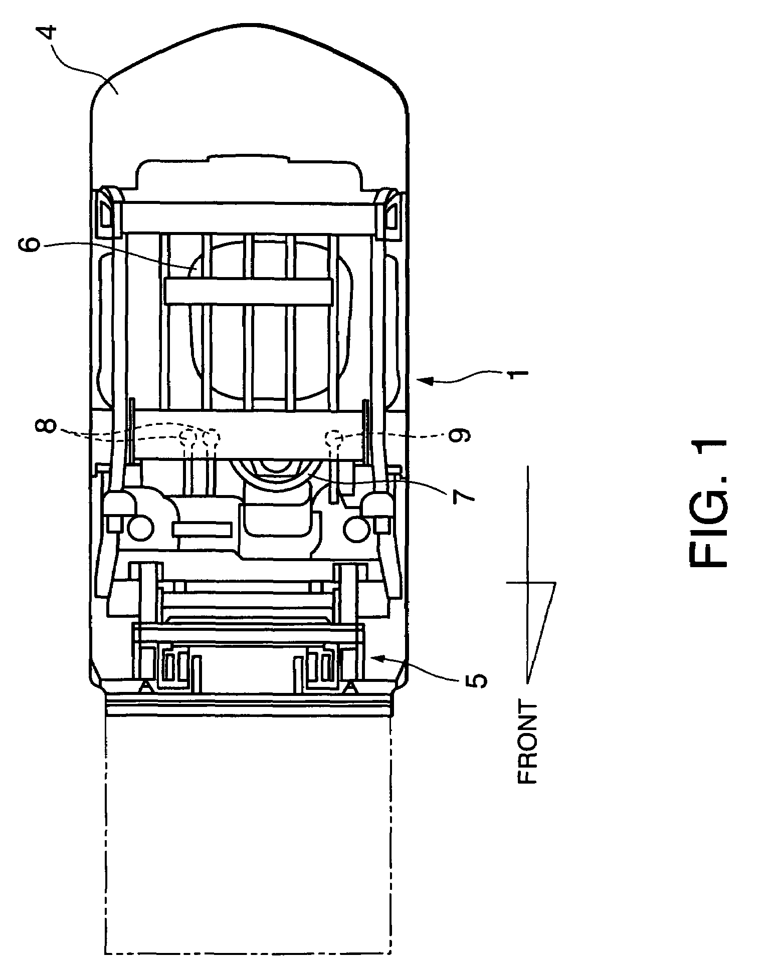
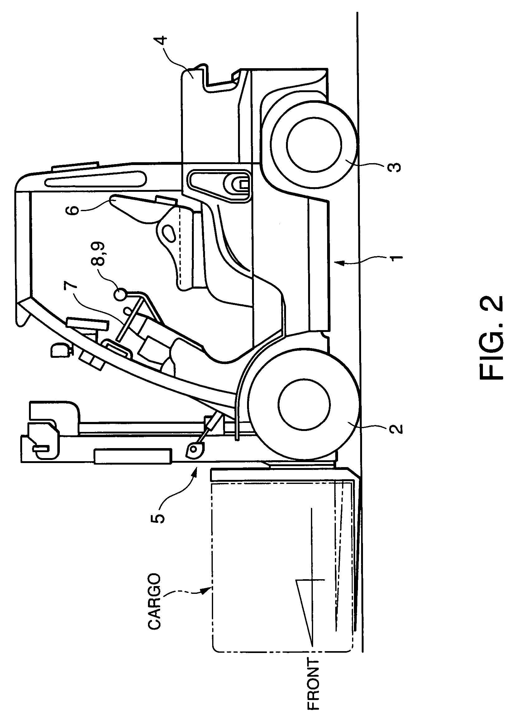
[0023]Referring to FIG. 1 and FIG. 2 of the drawings, a battery driven fork-lift truck comprises a pair of drive wheels 2 in a front most position of a vehicle body 1, and a pair of steered wheels 3 in a rear most position of the vehicle body 1. The pair of drive wheels 2 are driven respectively by a right wheel drive motor and a left wheel drive motor. The steered wheels 3 are disposed under a counter weight 4. The fork-lift truck further comprises a mast apparatus 5 disposed in front of the drive wheels 2 for handling cargos and an operator's cab 6 located between the pair of drive wheels 2 and the pair of steered wheels 3.

[0024]A steering wheel 7, a cargo handling control lever 8 for operating the mast device 5, a forward / rearward running control lever 9, an accelerator pedal, and a brake pedal are installed in the operator's cab 6. The forward / rearward running control lever 9 has three operating positions, forward running, neutral, and rearward running positions, which are selec...


PUM


Abstract

A priority flow rate control valve (30) distributes pressurized working oil discharged from a hydraulic pump (10) driven by an electric motor (11) to a power steering device (20) first, and distributes the residual pressurized working oil to a cargo handling device (19). The rotation speed of the electric motor (11) and the distribution ratio of the pressurized working oil of the priority flow rate control valve (30) vary depending on the operation states of these devices (19, 20). By decreasing the rotation speed of the electric motor (11) at a rate smaller than a normal decrease rate when the cargo handling device (2) stops operation in a state where the power steering device (20) and the cargo handling device (19) are in operation, a kickback in a steering wheel (7) due to a response delay of the priority flow rate control valve (30) can be prevented.

Description

FIELD OF THE INVENTION[0001]This invention relates to hydraulic pressure supply control for power steering and cargo handling of an industrial vehicle such as a fork-lift track.BACKGROUND OF THE INVENTION[0002]JPH05-005658U published by the Japan Patent Office in 1993 discloses a hydraulic pressure supply device which supplies pressurized working oil to a power steering device and a cargo handling device of an industrial vehicle such as a fork-lift truck, from a single hydraulic pump via a priority flow rate control valve.[0003]The hydraulic pump is driven by an electric motor. The steering operation and cargo handling operation performed by the operator of the vehicle are respectively detected by sensors, and a controller performs chopper control of the electric motor based on the detection data by the sensors such that the discharge amount of the pressurized working oil by the hydraulic pump satisfies the working oil amount which is required by the power steering device and the ca...

Claims


Application Information

Patent Timeline
Patent Type & Authority Patents(United States)
IPC IPC(8): F16D31/02
CPCB62D5/065B62D5/075B66F9/07568B66F9/07572
Inventor YOSHIDA, NAOKIINOUE, KIYOSHIWAGATSUMA, MAKOTOTAKAMURA, TORU
Owner NISSAN FORKLIFT CO LTD
Why Eureka
Try Eureka