Engine for motorcycle

a technology for motorcycles and engines, applied in machines/engines, cycle equipment, gearing, etc., can solve the problems of poor mountability and workability of rotation shafts, and achieve the effects of compact structure, improved workability of engine cases, and improved assembly efficiency

Active Publication Date: 2008-04-08
SUZUKI MOTOR CORP
View PDF5 Cites 9 Cited by
  • Summary
  • Abstract
  • Description
  • Claims
  • Application Information

AI Technical Summary

Benefits of technology

[0009]The present invention was conceived in consideration of the circumstances mentioned above, and an object of the invention is to provide an engine for a motorcycle having a compact structure capable of improving and enhancing the workability of an engine case and the assembling efficiency thereof.
[0017]According to the present invention of the characters mentioned above, the transmission output shaft can be disposed below the other rotation shafts. This can reduce the longitudinal (front-rear direction) length of the engine case and also reduce the total size of the engine. Since a single mating surface is provided in the engine case, the workability of the engine case and mountability of the rotation shafts can be enhanced.
[0018]In addition, it is possible to reduce the space occupied by the rotation shafts in the front-rear direction, to effectively utilize the spaces on the front and rear sides of the crankshaft, and to mainly reduce the front-rear size of the engine case.
[0019]The transmission output shaft can be placed close to the crankshaft. This can enhance the space occupation efficiency inside the engine case and can reduce the front-rear size of the engine case.
[0020]Furthermore, according to the present invention, it is possible to reduce the center distance between the transmission input shaft and the transmission output shaft, and the size of the engine case. It is also possible to smoothly insert the transmission output shaft in the engine case so that the transmission driven gears mounted on the transmission output shaft do not interfere with a transmission driving gear mounted on the transmission input shaft. Accordingly, the mountability of the transmission output shaft can be enhanced.

Problems solved by technology

Moreover, since the engine case has a three-splittable structure, the workability thereof and mountability of the rotation shafts are not good.

Method used


Image

  • Engine for motorcycle
  • Engine for motorcycle
  • Engine for motorcycle

Examples


Embodiment Construction

[0036]An embodiment of the present invention will be described hereunder with reference to the accompanying drawings. Further, it is to be noted that terms “upper”, “lower”, “right”, “left” and the like terms are used herein with reference to the illustration of the drawings or in a general standing state of the motorcycle to which the engine is mounted.

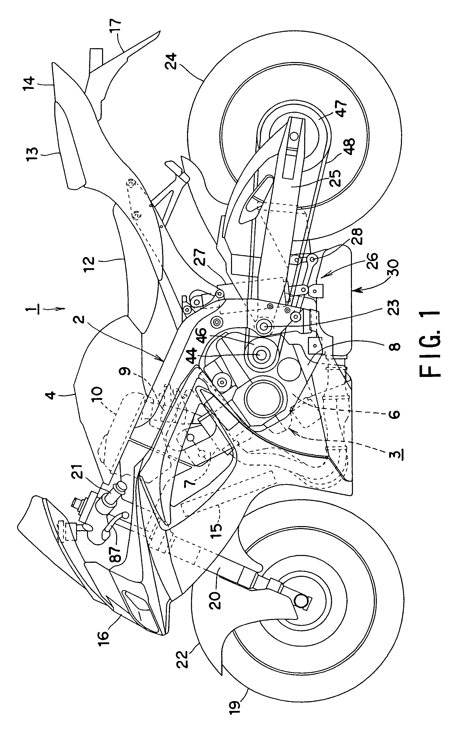
[0037]With reference to FIGS. 1 and 2 showing the embodiment of the present invention, a motorcycle 1 includes a body frame 2 made of, for example, aluminum. A water-cooled four-cycle engine 3 including four cylinders arranged in parallel is suspended from the front half portion of the body frame 2, and a fuel tank 4 is mounted on the body frame 2 above the engine 3.

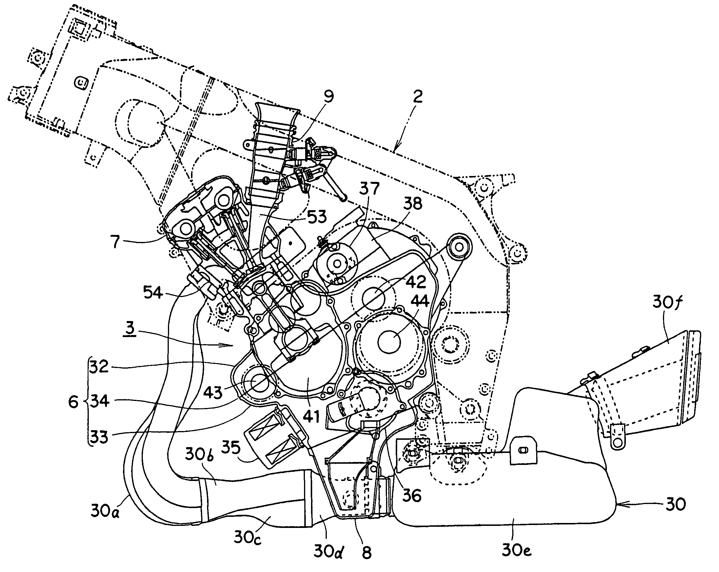
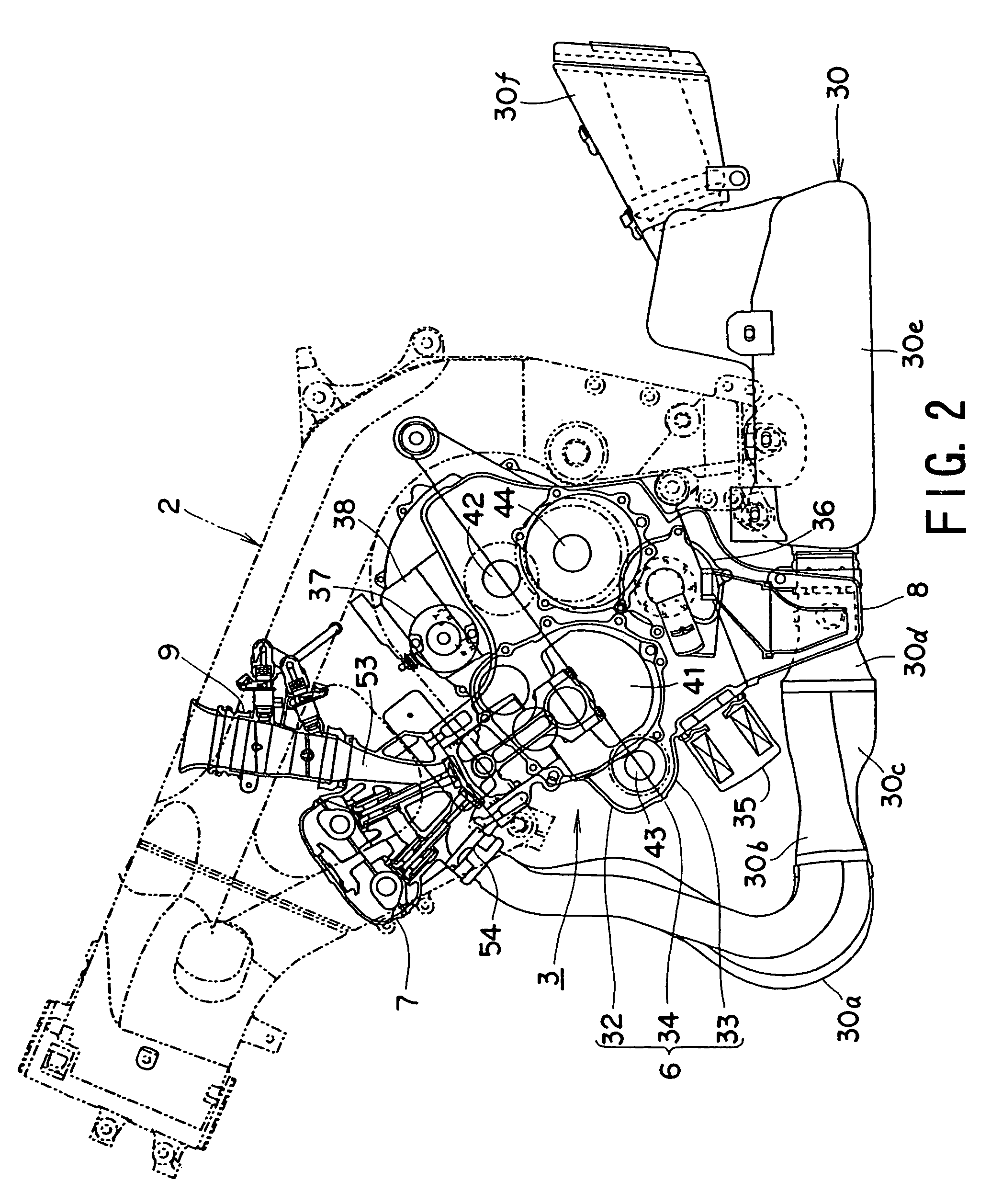
[0038]In the engine 3, a cylinder assembly 7 is disposed on the upper front side of an engine case 6, and an oil pan 8 is disposed on the lower side of the engine case 6. A fuel injector (throttle body) 9 is connected to the rear portion of the cylinder assembly 7, and an...


PUM


Abstract

An engine for a motorcycle includes an engine case split in an upper case section and a lower case section. A mating surface between the upper case section and the lower case section extends linearly and inclines forward downward in a side view of the motorcycle. A crankshaft, a transmission input shaft, and a balancer shaft extending in the width direction of the motorcycle are rotatably supported at the mating surface, and a transmission output shaft rotated by the transmission input shaft is supported in the lower case section. The balancer shaft, the crankshaft, and the transmission input shaft are arranged in that order from the front side in the running direction of the motorcycle. The transmission output shaft is disposed below the transmission input shaft.

Description

BACKGROUND OF THE INVENTION[0001]1. Field of the Invention[0002]The present invention relates to an engine for a motorcycle (motorcycle engine) improving an arrangement of various rotation shafts in an engine case.[0003]2. Related Art[0004]Prior arts provide, for example, Japanese Unexamined Patent Application Publication No. 2002-122028 (patent publication 1) and No. 2004-360773 (patent publication 2), which disclose structures for arranging rotation shafts, such as a crankshaft, a transmission input shaft, a transmission output shaft, and a balancer shaft (i.e., secondary balancer shaft), in an engine case of a motorcycle engine.[0005]In the engine disclosed in the patent publication 1, the engine case is split into three sections, namely, an upper case section, a middle case section, and a lower case section. A crankshaft and a secondary balancer shaft are rotatably supported at a mating or joint surface between the upper case and the middle case, and a transmission input shaft a...

Claims


Application Information

Patent Timeline
Patent Type & Authority Patents(United States)
IPC IPC(8): F02F7/00F16H57/02B62M7/02F02B61/02F16F15/26
CPCB62M25/04F02B61/02F16H3/089Y10T74/2186F16H2200/0052Y10T74/19223
Inventor ODA, TOMOYUKIARAKAWA, HIDETOSHI
Owner SUZUKI MOTOR CORP
Why Eureka
Try Eureka