
Intermodel truck

a truck and model technology, applied in the field of vehicles, can solve the problems of wasting time and money, unable to achieve the effect of achieving the effect of reducing labor intensity, and avoiding the use of labor intensity,

Active Publication Date: 2008-04-08
GERMAN STEVE
View PDF12 Cites 10 Cited by
  • Summary
  • Abstract
  • Description
  • Claims
  • Application Information

AI Technical Summary

Benefits of technology

[0006]The present device is a combination shipping container and vehicle that may be handled and lifted in a similar fashion to a standard shipping container, and also provide its own motive force for driving as a vehicle. The combination container and vehicle may be lifted by a crane, or similar container lifting device onto a ship, a rail car, or the like. Upon unloading, the combination may be driven under its own power as a vehicle, making the combination extremely versatile in how it is used and handled.
[0010]At least two corner fittings are included in upper forward corners of the driver's cab for facilitating lifting of the combination by the crane. The corner fittings are each made of rigid, strong metallic material and are rigidly connected to the combination such that the combination may be safely lifted and handled thereby.

Problems solved by technology

The bottlenecks in such cargo operations are typically due to the limited number of trucks available for transporting the containers from either the destination port or the end rail terminal to the final destination.
As a result, cargo can sit idle for days while a limited number of trucks make their runs clearing the stacks of cargo containers.
Heretofore, no such practical method has been devised.
Further, such a needed container design would be only slightly heavier than a standard shipping container to maintain efficiency in cargo operations using such a device.

Method used


Image

  • Intermodel truck
  • Intermodel truck
  • Intermodel truck

Examples


Embodiment Construction

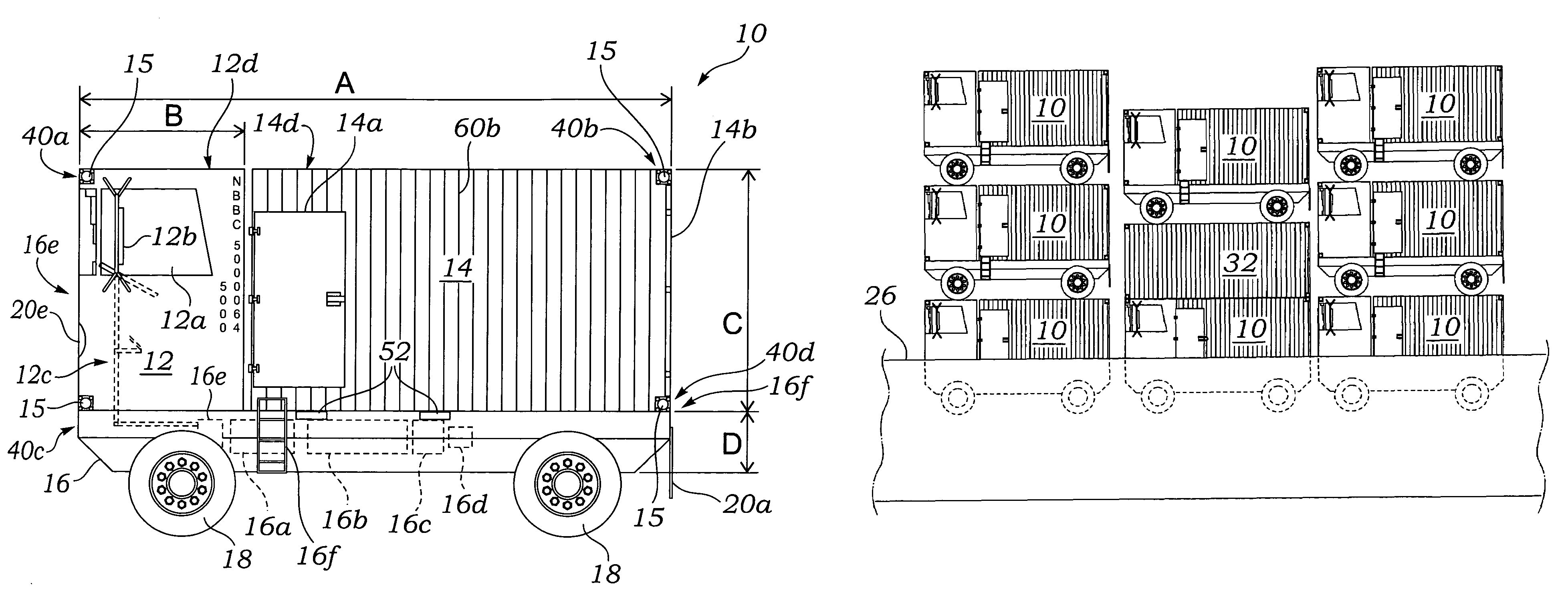
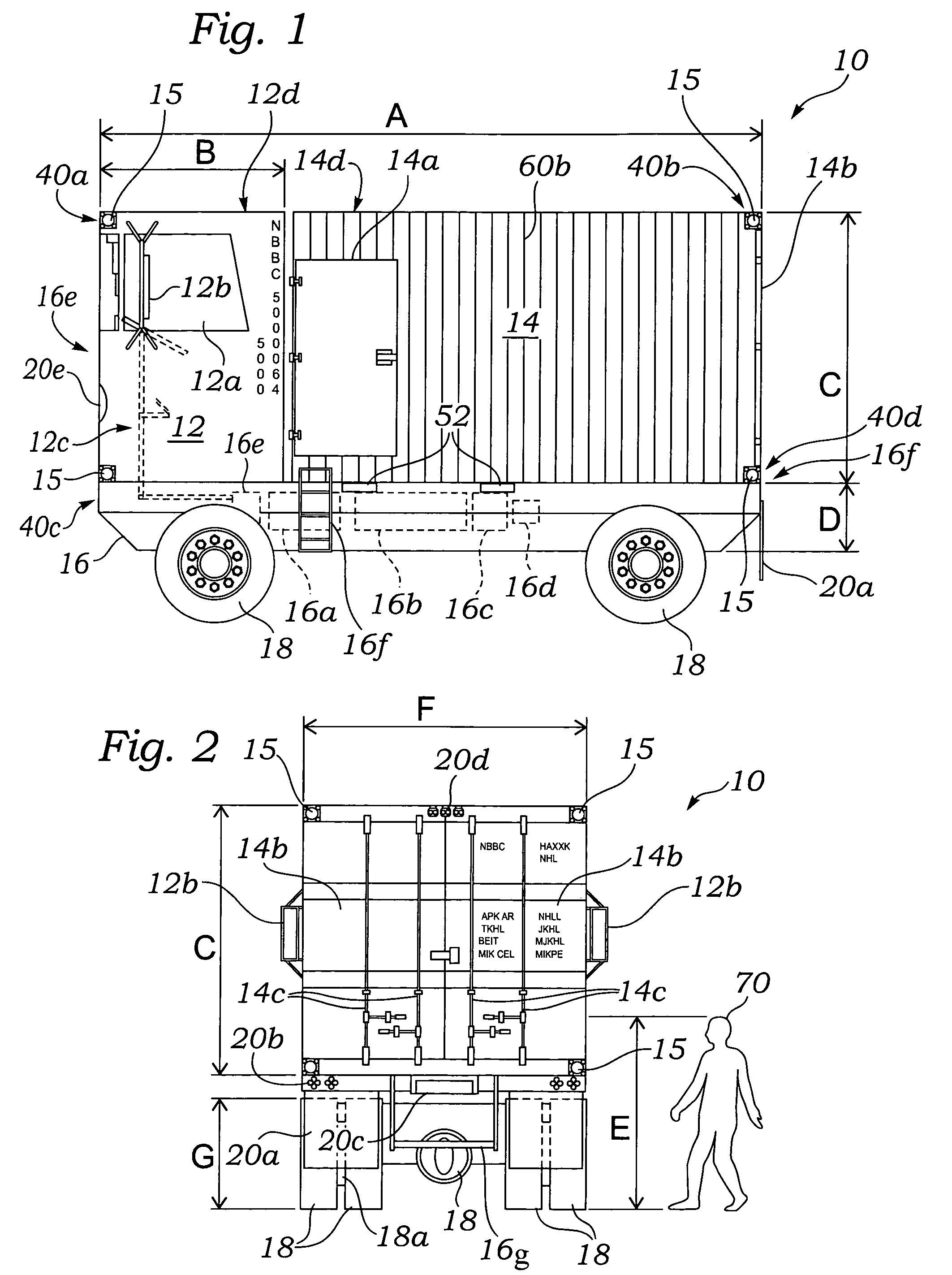
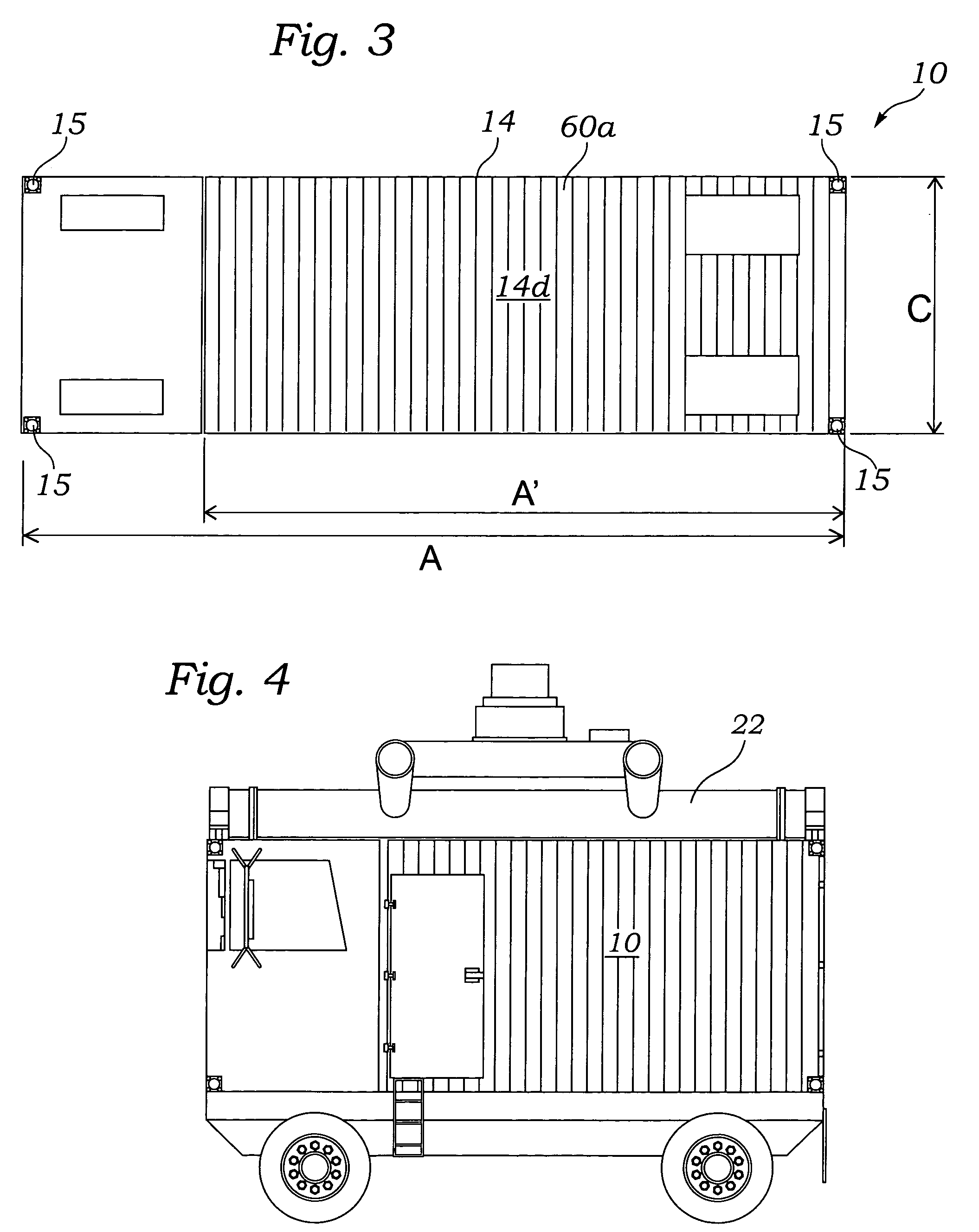
[0020]FIG. 1 illustrates a combination shipping container and vehicle 10 that may be handled and lifted in a similar fashion to a standard ISO shipping container 32 (FIG. 5), and also provide its own motive force for being driven as a vehicle. The combination 10 may be lifted by a crane 22, or similar container lifting device (FIG. 4) onto a ship 26 (FIG. 5), a rail car 29 (FIG. 6), or the like. Upon unloading the combination 10 may be driven under its own power as a vehicle, making the combination 10 extremely versatile in how may be used and handled.

[0021]The combination 10 includes a vehicle frame 16 that is generally the length A and width F of the standard shipping container 32, typically twenty or forty feet and eight feet, respectively. The frame 16 provides a strong support framework for the combination 10, and is comprised of a strong rigid material such as iron, or the like. The frame 16 preferably includes two generally horizontal and parallel forklift pockets 52 therein,...


PUM


Abstract

A combination shipping container and vehicle is disclosed that may be handled and lifted in a similar fashion to a standard shipping container, and also may provide its own motive force for driving as a vehicle. The combination includes a vehicle frame that is generally the length and width of the standard shipping container. The frame provides a strong support framework for the combination. An engine is supported by the frame, and a suspension supports at least four wheels by the frame. A transmission mounted to the frame transfers rotational energy from the engine to at least two of the wheels through a transfer case and an axle. A driver's cab is fixed to and above the frame at a forward end thereof and includes driver controls for controlling the engine, steering and braking of at least two of the wheels, and other related motor vehicle functions. A container portion is fixed to and above the frame at a rear end thereof. The container portion is substantially hollow and is adapted for cargo to be transported therein. The length and width of the combination is approximately that of a standard shipping container, and the overall height of the combination is the height of the standard shipping container plus the height of the frame plus half of a height of the wheels. The frame may further include a license plate holder, a flap for each wheel, and any other required equipment to conform to vehicular laws in various jurisdictions.

Description

CROSS-REFERENCE TO RELATED APPLICATIONS[0001]This application claims the benefit of U.S. Provisional Patent Application 60 / 597,913, filed on Dec. 23, 2005.FIELD OF THE INVENTION[0002]This invention relates to vehicles, and more particularly to a shipping container vehicle.DISCUSSION OF RELATED ART[0003]Standard ISO (International Shipping Organization) shipping containers are used throughout the world to transport cargo and goods. Typically such containers are loaded onto a ship at a port of origin, shipped to a destination port, unloaded into stacks, and then transported by rail or flatbed truck to their subsequent destinations. Stacks of unloaded containers may sit for days before suitable transportation equipment is available to take each container to its next destination. The bottlenecks in such cargo operations are typically due to the limited number of trucks available for transporting the containers from either the destination port or the end rail terminal to the final destin...

Claims


Application Information

Patent Timeline
Patent Type & Authority Patents(United States)
IPC IPC(8): B61D45/00
CPCB60P1/6418B60P3/08B61D3/20B65D88/121B65D90/18
Inventor GERMAN, STEVE
Owner GERMAN STEVE
Learn More