Pole terminal

a pole terminal and conductive body technology, applied in the direction of electrically conductive connections, coupling device connections, electrical apparatus, etc., can solve the problems of difficult production, complex configuration of the conductive body of the known pole terminal, and the low conductivity of the material suitable for cutting machining, so as to improve the haptics and optics

Inactive Publication Date: 2008-04-08
THORNER WOLFGANG B
View PDF13 Cites 17 Cited by
  • Summary
  • Abstract
  • Description
  • Claims
  • Application Information

AI Technical Summary

Benefits of technology

[0012]At its end facing away from the housing, the insulating body is screwed together with a tensioning nut, by way of a saw-tooth thread. By way of a circumferential projection on the circumference of the insulating body and by way of projections on the inside of the tensioning nut, the movements of the nut are limited to such a dimension, in the axial direction, that it merely allows introduction and tensioning of the external electrical conductor. This automatic screw lock furthermore prevents the nut from being screwed off again.
[0013]It is advantageous that the tensioning nut consists of insulating material. As a result, the tensioning nut cap can be made of metallic material. This significantly improves both the haptics and the optics. A pressure ring is mounted to rotate between the tensioning nut and the surrounding tensioning nut cap, by way of a projection that runs around the external circumference of the tensioning nut, and a ring shoulder in the pressure ring. The pressure ring is axially moved by the tensioning nut. In this way, an external conductor introduced into the conductive body can be braced against a cap made of insulating material, which rests against the housing. A metallic ring having an exclusively optical function is laid into this insulating cap.

Problems solved by technology

It is disadvantageous that a material that is suitable for cutting machining demonstrates a lower conductivity than the conductive material of the conductor to be connected, for example.
However, they are not suitable for cutting machining.
It is furthermore disadvantageous that the conductive bodies of the known pole terminals, as lathed parts, are configured in complex manner and are difficult to produce.

Method used


Image

  • Pole terminal
  • Pole terminal
  • Pole terminal

Examples


Embodiment Construction

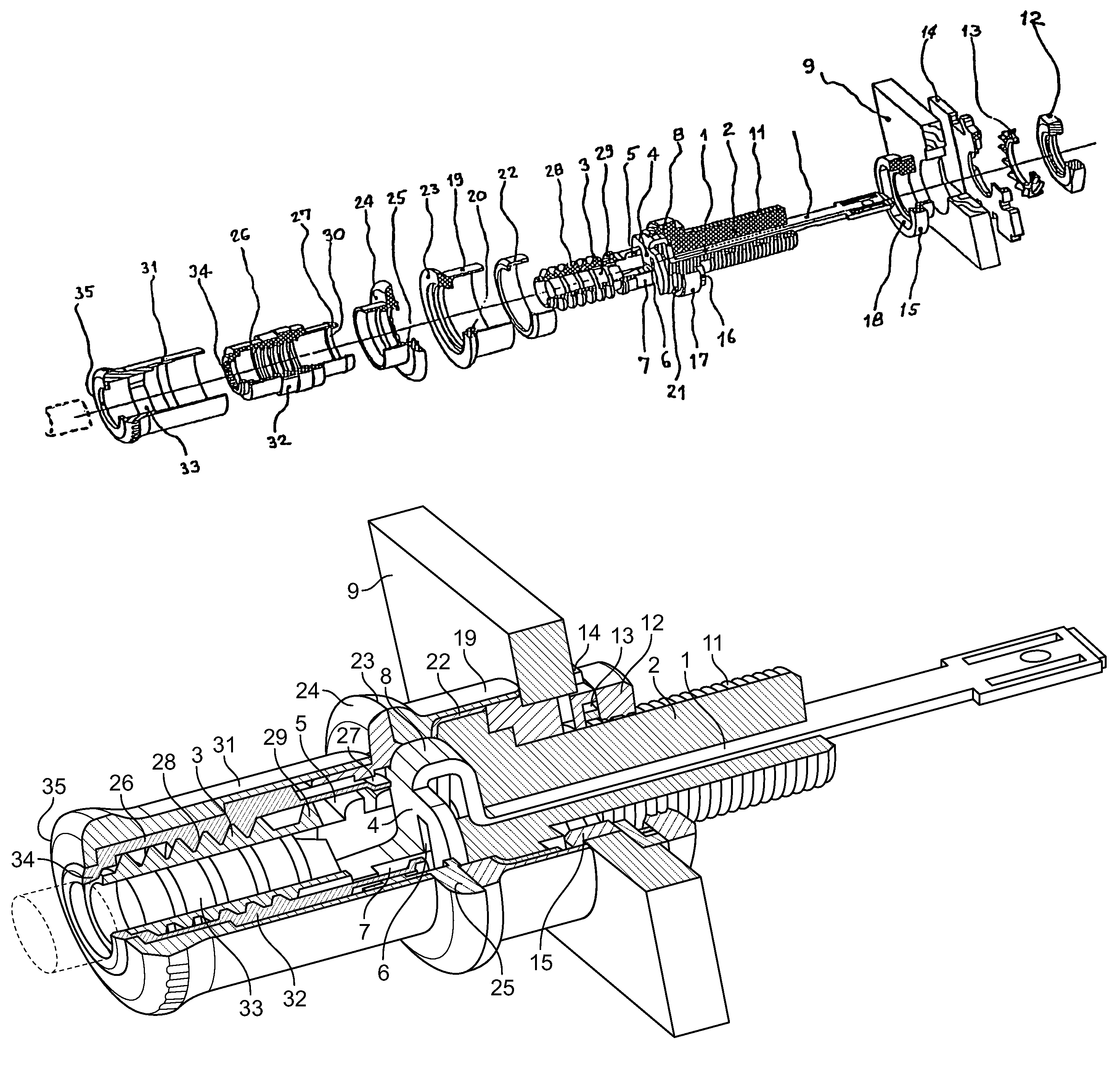
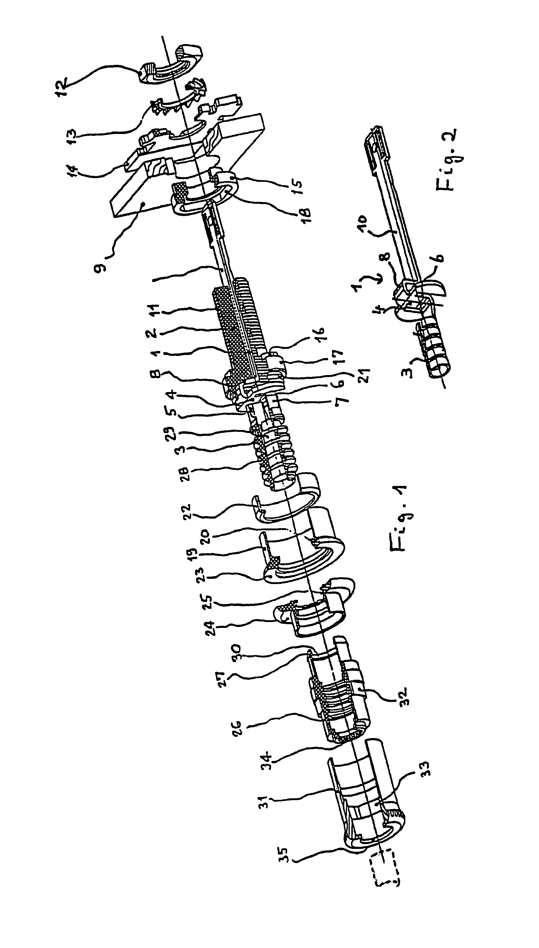
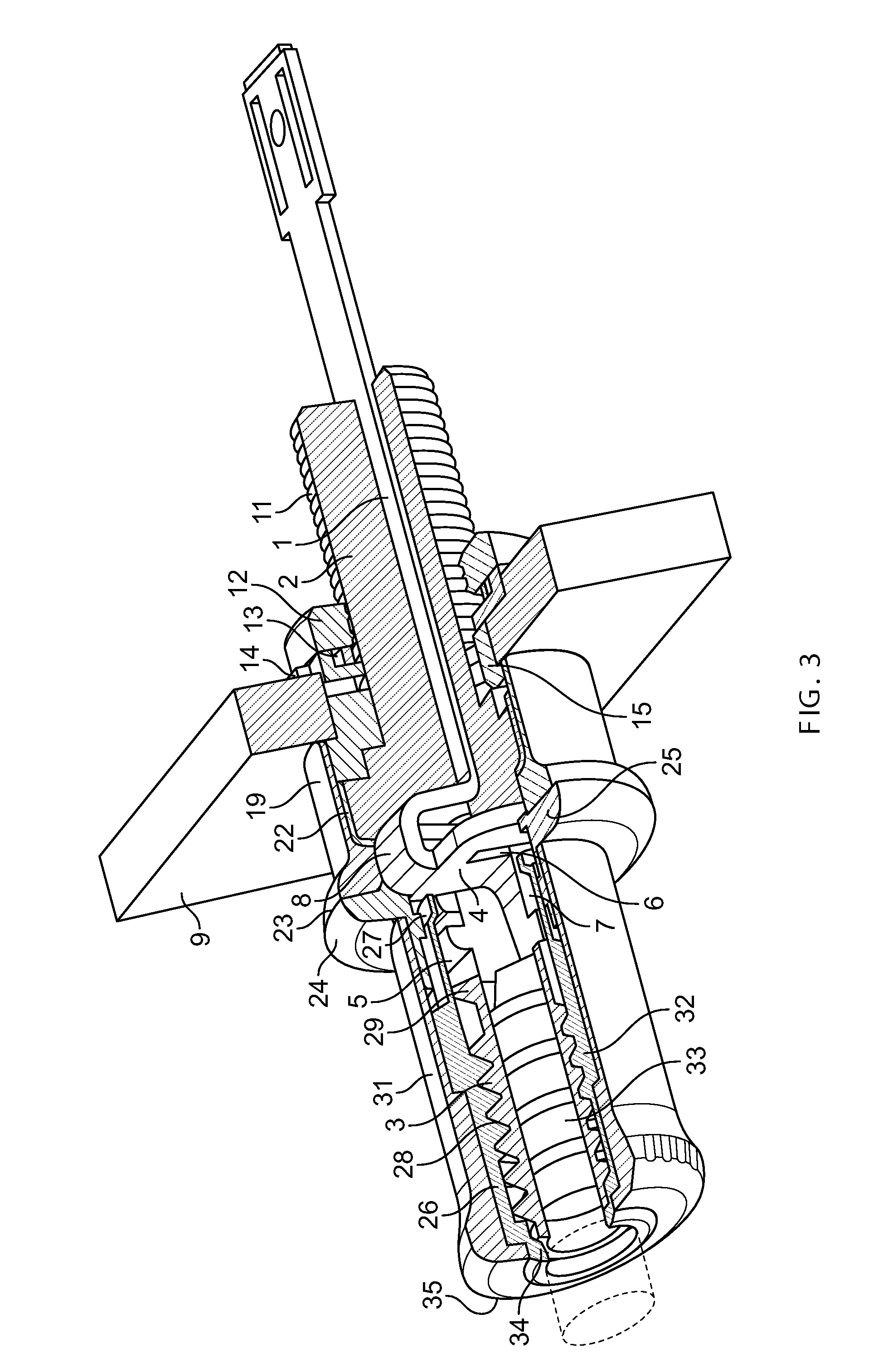
[0018]The pole terminal shown essentially consists of a metallic conductive body 1 that forms a composite body 1, 2 with a surrounding insulating body 2.

[0019]For connecting a banana plug, not shown, the conductive body 1 has a ring-shaped contact surface 3, parallel to its longitudinal axis, which is produced by means of bending technology. This surface is configured as a ridge with rings subsequently punched out crosswise to the longitudinal axis.

[0020]The continued conductive body 1 has a contact surface 4, produced by means of bending technology and running both parallel and crosswise to the longitudinal axis, for an external electrical conductor, not shown. The access to the contact surface 4 for the external conductor is made possible by an opening 5 in the insulating body 2. The contact surface 4 is widened crosswise to the longitudinal axis, and has slit-like recesses 6, in which the insulating body 2 engages with flattened shanks 7. Subsequent to the contact surface, the co...


PUM


Abstract

The invention relates to a pole terminal for producing an electrical connection. Said pole terminal comprises a metallic conductive body which is surrounded by an insulating body which can be fixed to the housing of an electrical appliance, and on which a tensioning nut can be screwed, said tensioning nut clamping the electrical conductor to be connected against the conductive body, establishing an electrical contact. The aim of the invention is to improve one such pole terminal in such a way that the conductive body can be produced from a material which is highly conductive, such as silver or copper. To this end, the conductive body is produced from a material exhibiting higher conductivity, by means of noncutting deformation, and is connected to the surrounding insulating body to form a composite body. Preferably, the conductive body is embodied as a stamped part which is machined by bending strain.

Description

CROSS REFERENCE TO RELATED APPLICATIONS[0001]Applicant claims priority under 35 U.S.C. §119 of German Application No. 102 04 373.6 filed Feb. 2, 2002. Applicant also claims priority under 35 U.S.C.§365 of PCT / EP02 / 14752 filed Dec. 24, 2002. The international application under PCT article 21(2) was not published in English.[0002]The invention relates to a pole terminal for producing electrical conductive connections, having a metallic conductive body that is surrounded by an insulating body that can be fixed to the housing of an electrical device, onto which a tensioning nut can be screwed, which clamps the electrical conductor to be connected against the conductive body, producing an electrical contact.BACKGROUND OF THE INVENTION[0003]Such pole terminals are used, to a great extent, in entertainment electronics, in order to couple lines and, in particular, loudspeakers to the amplifiers. They are characterized in that they allow easy manual coupling and uncoupling. Their conductive ...

Claims


Application Information

Patent Timeline
Patent Type & Authority Patents(United States)
IPC IPC(8): H01R9/05H01R13/10H01R13/02H01R13/73H01R24/00H01R24/10H01R24/76H01R101/00
CPCH01R24/20H01R2101/00
Inventor THORNER, WOLFGANG B.
Owner THORNER WOLFGANG B
Why Eureka
Try Eureka