Thermal displacement correcting device

a technology of displacement correction and correcting device, which is applied in the direction of manufacturing tools, instruments, process and machine control, etc., can solve the problems of prohibiting high-precision correction, and reducing the accuracy of machining, so as to achieve high precision and high accuracy

Inactive Publication Date: 2008-04-08
DMG MORI CO LTD
View PDF17 Cites 7 Cited by
  • Summary
  • Abstract
  • Description
  • Claims
  • Application Information

AI Technical Summary

Benefits of technology

[0012]The present invention was brought about taking into consideration the above-described problems, and it is an object of the present invention to provide a thermal displacement correcting device capable of determining with high precision a correction amount for canceling out the thermal displacement axially of a tool attached to a machine-tool spindle, to perform machining with high accuracy.
[0015]According to the thermal displacement correcting device of the present invention, the temperature directly before use of the tool to be attached to the spindle by the tool change is estimated, the tool temperature during use is estimated on the basis of the estimated tool temperature directly before use, etc., and the thermal displacement of the tool axially (correction amount) is estimated on the basis of the estimated tool temperature during use. Thus, the thermal displacement (correction amount) can be estimated with high precision, realizing machining with high accuracy.
[0023]Each of the tool temperature estimating unit and the correction setting unit may estimate the tool temperature directly before use, the tool temperature during use, and the thermal displacement of the tool axially on the basis of different estimation parameters for each tool. Each of the log information updating unit, the tool temperature estimating unit, and the correction setting unit may estimate the actual temperature of the tool, the tool temperature during use, and the thermal displacement of the tool axially on the basis of different estimation parameters for each tool. Thus, even if the tool behave differently from each other due to the differences in length, diameters, materials, coefficient of linear expansion, etc., it is possible to estimate the tool temperature directly before use, the tool actual temperature, the tool temperature during use, and the thermal displacement of the tool axially more precisely.
[0024]The thermal displacement correcting device further comprises a spindle temperature estimating unit for estimating a temperature of the spindle on the basis of an operational status of the spindle device obtained from the controller, and the tool temperature estimating unit estimates the tool temperature during use on the basis of the temperature of the spindle estimated by the spindle temperature estimating unit. This eliminates the need of a sensor for measuring temperature of the spindle, capable of reducing a manufacturing cost, and preventing a device configuration from being complicated.
[0025]As described above, according to the thermal displacement correcting device of the present invention, a temperature directly before use of the tool to be attached to the spindle by the tool change is estimated, on the basis of the estimated tool temperature directly before use, etc. a tool temperature during use is estimated, and, a thermal displacement (correction amount) of the tool axially is estimated on the basis of the estimated tool temperature during use. Thus, the thermal displacement (correction amount) can be estimated with high precision, realizing machining with high accuracy. Also, estimating the temperature of the spindle on the basis of the operational status of the spindle device obtained from the controller eliminates a need of a sensor for measuring temperature of the spindle, capable of reducing a manufacturing cost and preventing the device configuration from being complicated.

Problems solved by technology

This elongating of a tool degrades its machining accuracy.
Furthermore, a tool removed from the spindle and stowed in the tool magazine gradually cools, eventually arriving at a temperature at the same level as room temperature; but cooling to the room-temperature level takes a given amount of time.
Nonetheless, in the method in which a first machine-tool temperature near the spindle bearing, and a second machine-tool temperature of a region of the machine tool having high thermal stability are measured to estimate the thermal displacement of the tool—i.e., the above-described conventional thermal displacement correction technique—this point is not taken into consideration, which is prohibitive of performing high-precision correction.
A further problem with this conventional solution is that sensors for measuring the first machine-tool temperature and the second machine-tool temperature are required, raising production costs and complicating the device configuration.

Method used


Image

  • Thermal displacement correcting device
  • Thermal displacement correcting device
  • Thermal displacement correcting device

Examples


Embodiment Construction

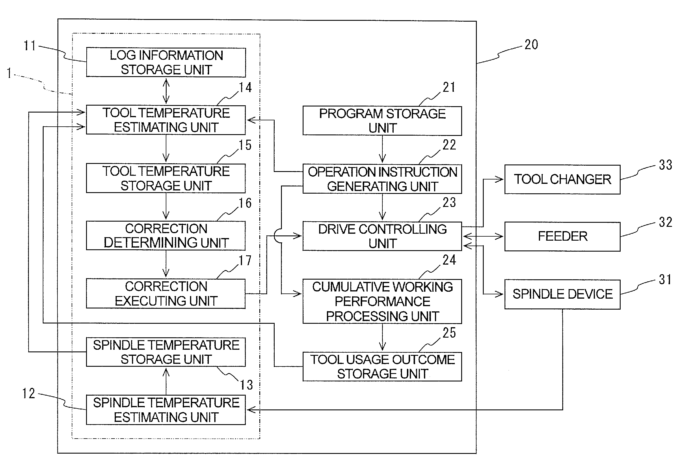
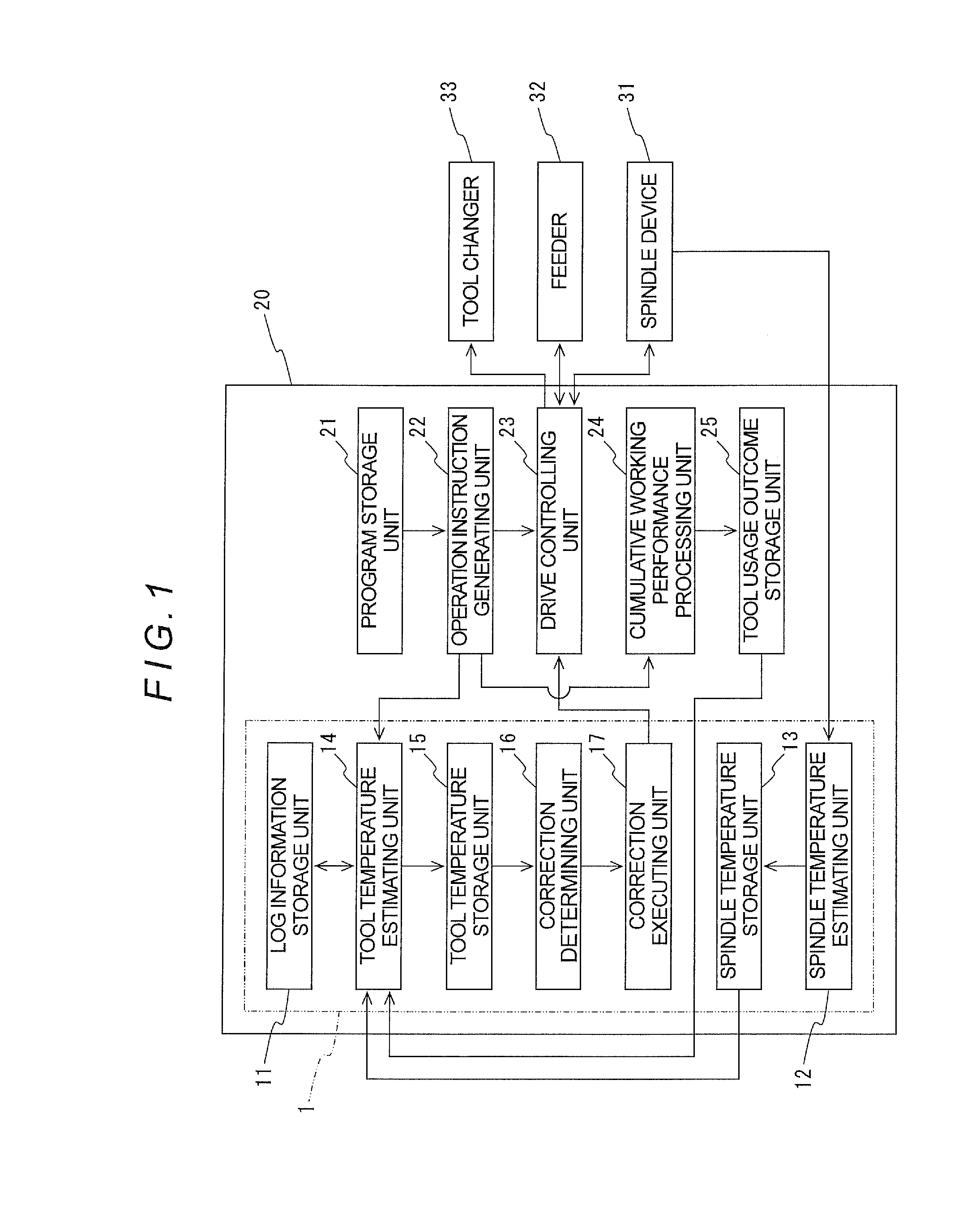
[0037]Detailed embodiments of the present invention will be explained with reference to the accompanying drawings. FIG. 1 is a schematic block diagram showing a thermal displacement correcting device of one embodiment of the present invention.

[0038]As shown in FIG. 1, a thermal displacement correcting device 1 of this example is made up of a log information storage unit 11, a spindle temperature estimating unit 12, a spindle temperature storage unit 13, a tool temperature estimating unit 14, a tool temperature storage unit 15, a correction setting unit 16, and a correction executing unit 17. The thermal displacement correcting device 1 is provided in a machine tool having a spindle device 31 placed movably in a vertical direction (along the Z-axis), for example, a table (not shown) mounted with a workpiece and placed movably in two-axis directions (along the X-axis and along the Y-axis) being orthogonal in the horizontal plane, a feeder 32 for moving the spindle device 31 along the ...


PUM

PropertyMeasurementUnit
thermal displacementaaaaaaaaaa
temperatureaaaaaaaaaa
tool temperatureaaaaaaaaaa

Abstract

Machine-tool thermal displacement correcting device having: a tool-temperature estimating unit for recognizing—based on identification data obtained from a controller for designating, out of tools stowed in the tool-changer tool magazine, an exchange-target tool—the directly-after-use temperature of the ID'd tool, and estimating the tool temperature directly before use, based on the recognized directly-after-use tool temperature and on lapsed time, obtained from the controller, since previous use of the ID'd tool, and for estimating, based on the estimated directly-before-use tool temperature and on the spindle temperature, during-use temperature of the tool; a correction determining unit for estimating, based on the estimated during-use tool temperature, axial thermal displacement of the tool, and determining a correction amount for canceling out the displacement; and a correction executing unit for carrying out correction based on the determined correction amount.

Description

BACKGROUND OF THE INVENTION[0001]1. Technical Field[0002]The present invention relates to thermal displacement correcting devices for correcting axial thermal displacement of a tool attached to the spindle of a machine tool.[0003]2. Description of the Related Art[0004]In machine-tool installations such as machining centers, the bearings that rotatably support the tool spindle run hot, such that the heat occurring due to the thermal emission is transferred to the spindle, and the tool chucked onto the spindle, and elongates the tool. This elongating of a tool degrades its machining accuracy.[0005]Against this backdrop, to prevent such degradation to machining accuracy, correction methods—an example of which is disclosed in Japanese Unexamined Pat. App. Pub. No. 2004-148443—of correcting tool thermal displacement along the spindle axis orientation have been proposed to date.[0006]The correcting method in JP 2004-148443 is performed by: measuring a first machine-tool temperature near t...

Claims


Application Information

Patent Timeline
Patent Type & Authority Patents(United States)
IPC IPC(8): B23Q3/157
CPCB23Q3/155B23Q11/0007Y10T483/13Y10T483/15Y10T483/10Y10T483/138Y10T409/303752
Inventor IEFUJI, NOBUHIKO
Owner DMG MORI CO LTD
Why Eureka
Try Eureka