
Method and apparatus for creating color conversion table

a color conversion and table technology, applied in the field of methods and apparatus for creating color conversion tables, can solve the problems of reducing the image quality of the image, and increasing the size of the table, so as to achieve the effect of limiting the effect of image quality

Inactive Publication Date: 2008-04-08
CANON KK
View PDF11 Cites 2 Cited by
  • Summary
  • Abstract
  • Description
  • Claims
  • Application Information

AI Technical Summary

Benefits of technology

[0011]Accordingly, an object of the present invention is to solve the above-mentioned problems individually or collectively and create a color conversion table from a color conversion table of any number of grids by downsampling grids while limiting effect upon image quality.

Problems solved by technology

However, the format of the above-described color conversion table is such that table size increases rapidly if use is made of a highly accurate color conversion table, namely a color conversion table having a large number of grid points.
For this reason, when it is attempted to perform a highly accurate color conversion as by a photo-direct printer that prints an image that has been recorded in an external memory such as compact flash ® (CF) card, problems arise because of hardware having a comparatively small storage capacity if use is made of a printer driver that includes a highly accuracy color conversion table.
However, a color conversion table of even smaller size cannot be created by downsampling an already created color conversion table having a size smaller than the full size.
At the portion where the continuous tone ink changes over, the point at which the dark ink starts appearing shifts and a decline in image quality, which is ascribable to downsampling of the color conversion table, tends to occur.
However, there are instances where a similar decline in image quality occurs when simple interpolation is applied by the same method to a 4-color or 3-color color conversion table for RGB→CMYK or RGB→CMY, or to a 3-color color correction table for RGB→R′G′B′.

Method used


Image

  • Method and apparatus for creating color conversion table
  • Method and apparatus for creating color conversion table
  • Method and apparatus for creating color conversion table

Examples


first embodiment

[0040][Structure]

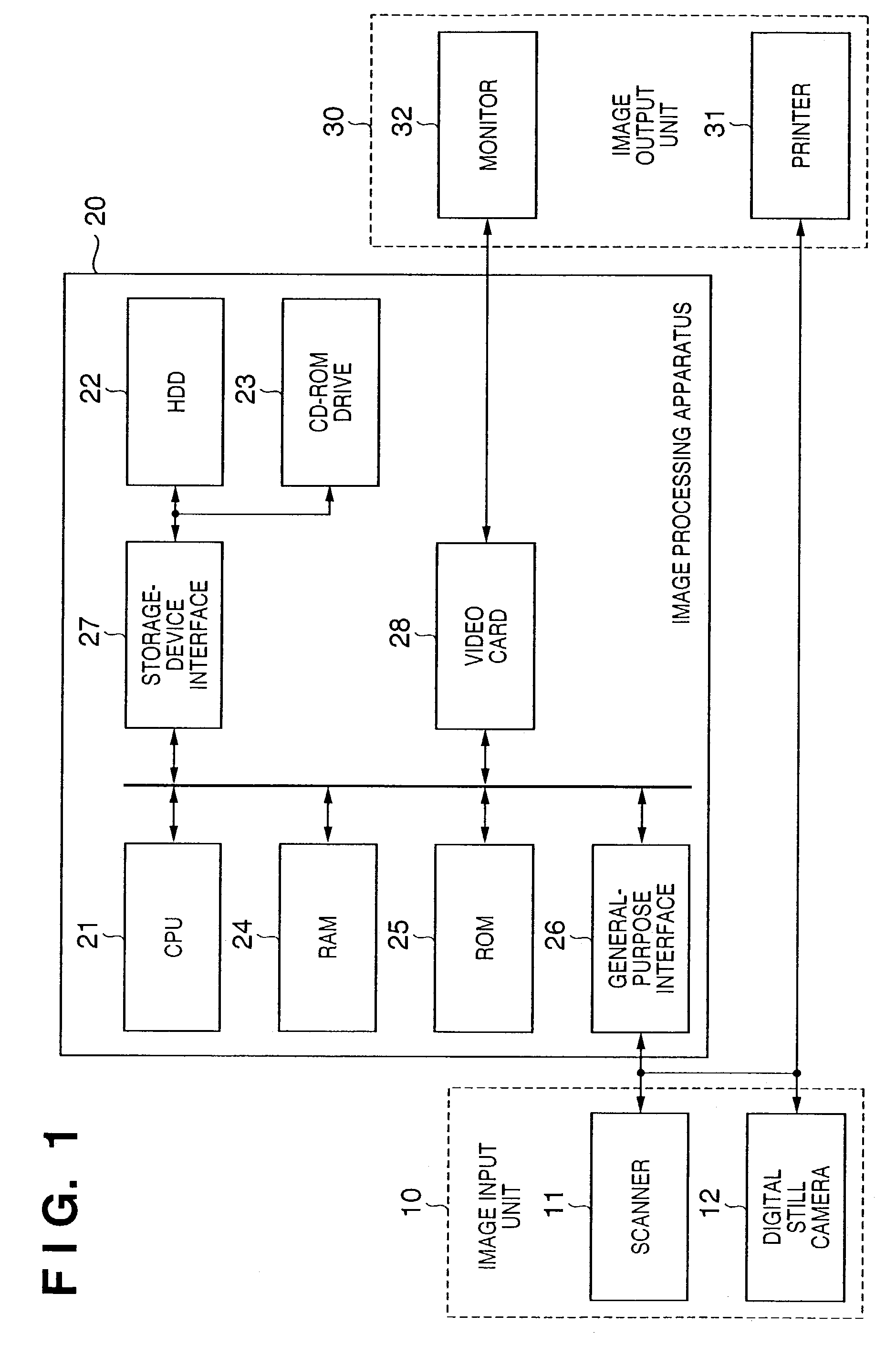
[0041]FIG. 1 is a block diagram illustrating the configuration of an image processing system according to a preferred embodiment of the present invention.

[0042]As shown in FIG. 1, the system includes an image input unit 10 comprising devices such as a film scanner or image scanner 11 and a digital still camera 12 capable of acquiring a color image. The image input unit 10 outputs image data (continuous tone color-specification data) representing the acquired color image.

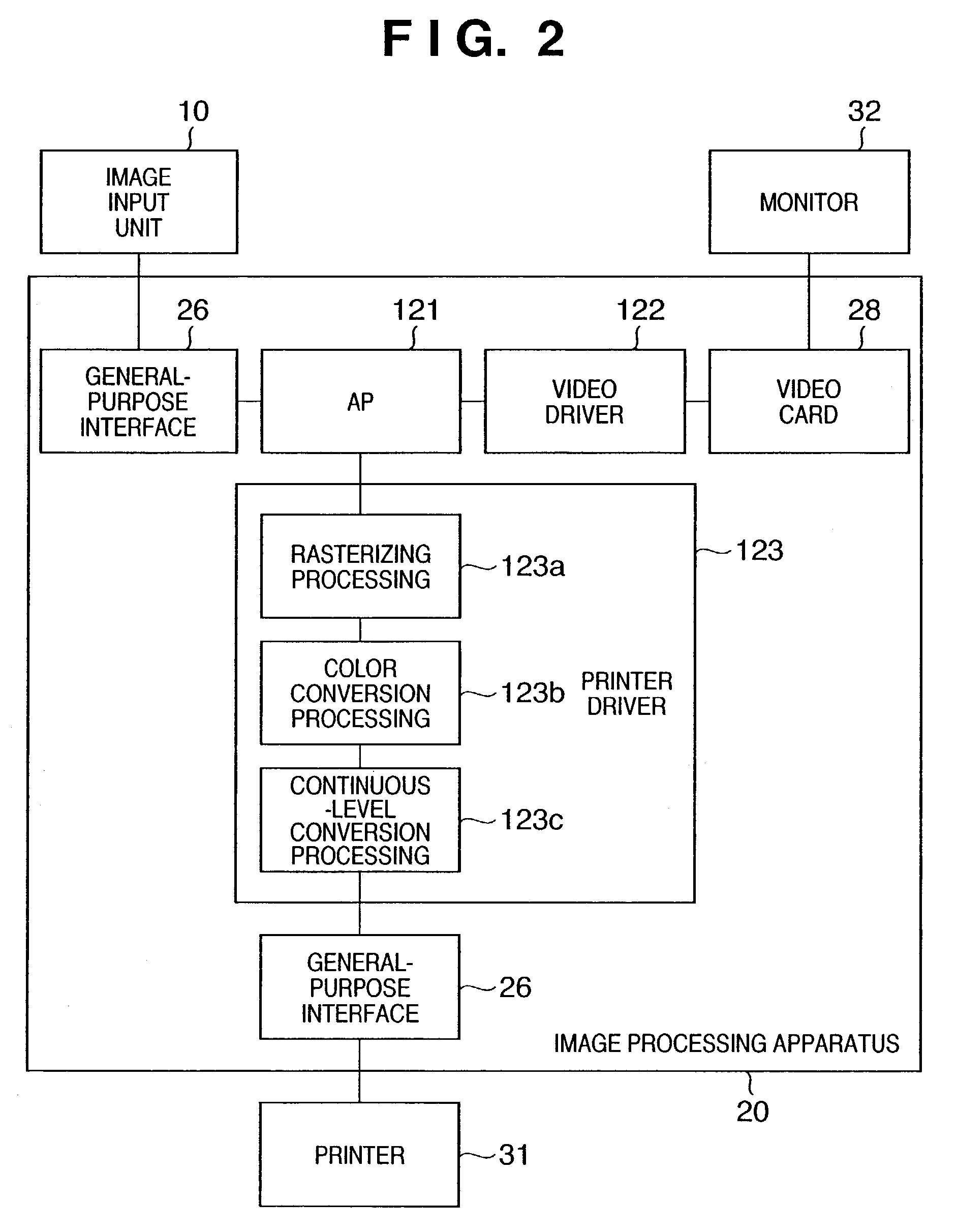
[0043]An image processing apparatus 20 comprising a personal computer or the like applies predetermined image processing to image data that is input via a general-purpose interface 26 such as a USB (Universal Serial Bus) or IEEE1394, and outputs image data representing result of this processing to an image output unit 30. It should be noted that a parallel interface such as an SCSI or GPIB or serial interface such as an RS232C or RS422 can also be utilized as the general-purpose interface 26.

[0044]Th...

second embodiment

[0099]An image processing apparatus according to a second embodiment of the invention will now be described. Components in this embodiment similar to those of the first embodiment are designated by like reference characters and need not be described again in detail.

[0100]In the second embodiment, a color conversion table having a specific number of grids is obtained as an output.

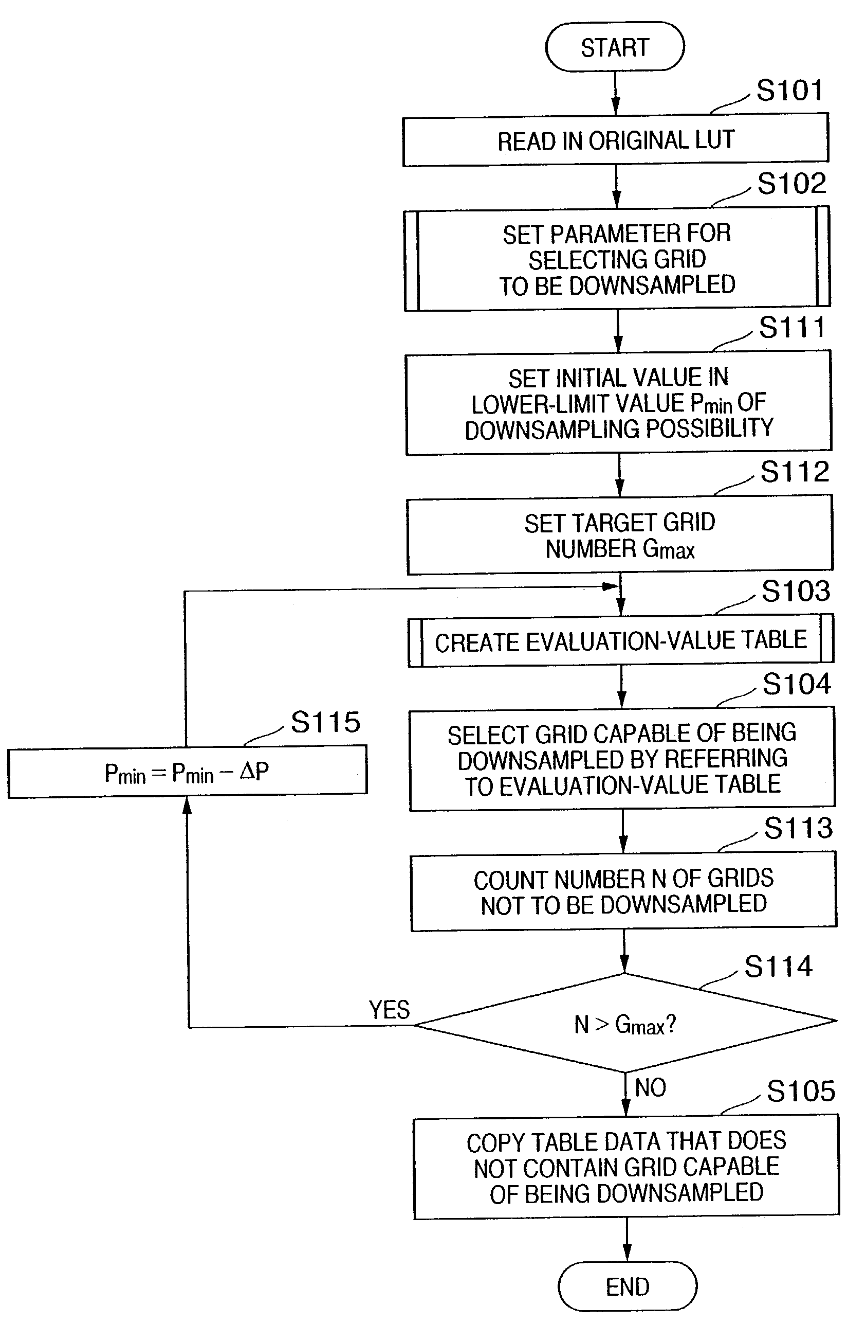
[0101]FIG. 16 is a flowchart useful in describing processing for downsampling a color conversion table according to a second embodiment of the present invention. Steps identical with those in FIG. 3 are designated by like step numbers and need not be described again in detail.

[0102]Following the writing of the original LUT (S101) and the setting of the selection parameter (S102) for grids to be downsampled (exclusive of the lower-limit value Pmin), “1” is set as the initial value of the lower-limit value Pin of downsampling possibility P (S111) and a target number Gmax of grids is set (S112).

[0103]Following ...


PUM


Abstract

If the grids of a color conversion table are simply downsampled, the way ink is used (the manner of the changeover in the value of a CMYKlclm signal) differs from that color conversion table before downsampling, there is a shift in the starting point of dark ink at the point of changeover of continuous tone ink, and a decline in image quality ascribable to downsampling of the color conversion table tends to occur. Accordingly, an original LUT is read in, a parameter for selecting a grid to be downsampled is set, a table of evaluation values for selecting a grid to be downsampled is created, a grid capable of being downsampled is selected by referring to the evaluation-value table, and table data that does not contain this grid is copied.

Description

FIELD OF THE INVENTION[0001]This invention relates to a method and apparatus for creating a color conversion table. More particularly, the invention relates to color conversion processing for transforming continuous tone color-specification data between spaces having different color specifications.BACKGROUND OF THE INVENTION[0002]A color printing system for printing a color image in association with a computer is known as a technique that utilizes a color conversion table for transforming continuous tone color-specification data between different color-specification spaces.[0003]The color image in a computer expresses tone by the three primary colors of red (R), green (G) and blue (B) for every pixel of pixels arrayed in horizontal and vertical directions. A color printer, on the other hand, prints in four colors, namely cyan (C), magenta (M), yellow (Y) and black (K), or in six colors, namely the above-mentioned four colors and, in addition, light cyan (lc) and light magenta (lm). ...

Claims


Application Information

Patent Timeline
Patent Type & Authority Patents(United States)
IPC IPC(8): H04N1/60G06K9/00B41J2/525G06T1/00H04N1/46
CPCH04N1/6019
Inventor TSUCHIYA, OKINORI
Owner CANON KK
Learn More