
Mode-locked laser with variable pulse duration

a mode-locked laser and variable pulse duration technology, applied in the field of solid-state mode-locked lasers, can solve the problems of not being operable in pulsed solid-state lasers, toxic and must be replaced and maintained, and high cost of lasers, and achieve fine pulse duration variability and coarse pulse duration variability

Active Publication Date: 2008-04-08
CONTINUUM ELECTRO OPTICS
View PDF10 Cites 4 Cited by
  • Summary
  • Abstract
  • Description
  • Claims
  • Application Information

AI Technical Summary

Benefits of technology

"The present invention is about a laser that can generate pulses with different durations. It uses a special absorber material called Cr4+:YAG, which can be placed in different positions and orientations to change the pulse duration. By adjusting these factors, the laser can produce pulses with a wide range of durations. This technology can be useful in various applications such as optical communication or material processing."

Problems solved by technology

By combining two different laser platforms, such a laser is both expensive and complicated to use.
While a dye solution operates fairly reliably, it may be toxic and must be replaced and maintained on a regular basis.
However, while these fast, solid-state SAs perform successfully in continuous-wave lasers, they have not been reported as being operable in pulsed, solid-state lasers.
Unfortunately, these conditions are difficult to obtain in pulsed, flashlamp-pumped Nd3+:YAG lasers.
Typically, this slow SA would not be capable of operating well on its own as a passive mode-locking element.

Method used


Image

  • Mode-locked laser with variable pulse duration
  • Mode-locked laser with variable pulse duration
  • Mode-locked laser with variable pulse duration

Examples


Embodiment Construction

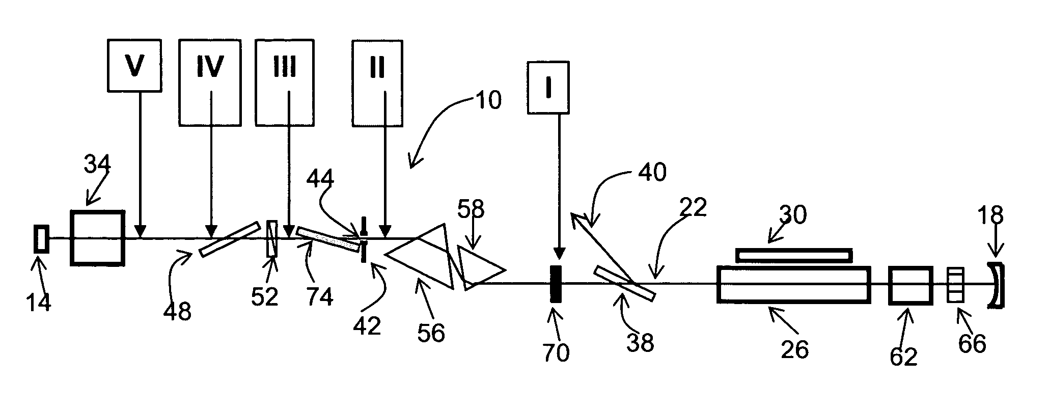
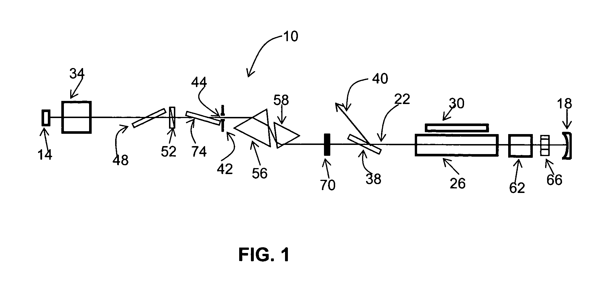
[0025]FIG. 1 is a schematic illustration of an exemplary embodiment of a laser 10 in accordance with the present invention. The laser 10 is arranged in a cavity (“resonator cavity”) which is bounded by a reflective surface 14 at one end (the “proximal” end) and another reflective surface 18 at an opposite end (the “distal” end). The reflective surfaces are preferably highly reflective, such as a highly reflective mirror. The reflective surfaces may be planar, convex, or concave, and are preferably, concave. The reflective surface 14 and the reflective surface 18 may differ in one or more characteristics, such as the degree of reflectivity, the degree of planarity or concavity, and the like. A pathway for radiant beams is established between the two surfaces 14 and 18, as schematically represented by line 22. The length of the beam pathway may be from about 50 cm to about 200 cm, and preferably, from about 80 cm to about 120 cm (e.g., 90 cm). The pathway for a beam making a round-tri...


PUM


Abstract

A pulsed, mode-locked, picosecond laser having a solid-state laser medium, a saturable absorber (SA), and a passive negative feedback (PNF) element. The SA is “slow,” having an absorption recovery time which is longer than a desired duration of an output pulse. The SA and the PNF element together mode-lock the laser to produce an output pulse or pulses of a given duration. The position of the SA along the beam path and the orientation of the SA with respect to the beam path can be varied to vary the output pulse duration over a wide range.

Description

FIELD OF THE INVENTION[0001]The present invention relates generally to lasers, and more particularly, to solid state mode-locked lasers capable of producing output pulses of different durations.[0002]U.S. Pat. No. 6,546,027 (hereinafter the “'027 patent”), entitled LASER SATURABLE ABSORBER AND PASSIVE NEGATIVE FEEDBACK ELEMENTS, AND METHOD OF PRODUCING ENERGY OUTPUT THEREFROM, which issued on Apr. 8, 2003, is herein incorporated by reference in its entirety.BACKGROUND INFORMATION[0003]Lasers producing picosecond output pulses, or “picosecond lasers,” are useful in many scientific applications. For example, a parametric laser cavity producing high-power, tunable, picosecond pulses, is useful for nonlinear optical studies of narrow-band transitions in the near- and mid-infrared spectral regions. Nd-based, solid-state lasers having an Nd-doped active medium, are the most common and widely used picosecond lasers.[0004]Generally, picosecond lasers, such as an Nd-based, solid-state laser,...

Claims


Application Information

Patent Timeline
Patent Type & Authority Patents(United States)
IPC IPC(8): H01S3/098H01S3/092H01S3/106H01S3/113H01S3/16
CPCH01S3/1068H01S3/1118H01S3/113H01S3/092H01S3/1611H01S3/1643
Inventor KHAYDAROV, DZHAKHANGIR V.
Owner CONTINUUM ELECTRO OPTICS
Learn More