Coriolis mass measuring device

a technology of density meter and mass measurement device, which is applied in the direction of volume metering, specific gravity measurement, instruments, etc., can solve the problems of considerable expense associated with the start-up of the transducer, the firmware stored and executed in the digital measuring circuit becomes correspondingly complex, and the measurement value production is required

Active Publication Date: 2008-04-15
ENDRESS HAUSER FLOWTEC AG
View PDF54 Cites 20 Cited by
  • Summary
  • Abstract
  • Description
  • Claims
  • Application Information

AI Technical Summary

Benefits of technology

[0048]The invention rests particularly on the recognition that the exciter power fed into the transducer for maintaining the lateral oscillations of the measuring tube can be influenced to a great degree by inhomogeneities in the medium to be measured, homogeneities such as e.g. entrained gas bubbles, entrained solid particles, and the like. If this exciter power, dependent on an apparent viscosity and / or a viscosity-density product of the medium guided in the measuring tube, is compared with an actual, or at least significantly more accurately measured, viscosity of the medium, obtained, for example, by a corresponding external and / or internal reference-measurement, the part instantaneously relevant for the mass flow measurement attributable to inhomogeneities in the medium can be estimated with sufficient accuracy. A special advantage of the invention is that even the reference measurement of the viscosity can be performed by means of the same Coriolis mass flow measuring device and, consequently, independently of possible external measurement locations.
[0049]A further advantage of the invention is that, in the case of the Coriolis mass flow measuring device of the invention, as compared to a conventional device, there is need for small changes only in the usually digital measurement production, essentially limited to the firmware, while, both in the case of the transducer and also in the case of the production and pre-processing of the oscillation measurement signals, no, or only very slight, changes are required. Thus, for example, the oscillation measurement signals can be sampled, as before, with a usual sampling ratio of far below 100:1, especially about 10:1.

Problems solved by technology

However, there is a significant disadvantage of such classifiers, among other things, in that, compared to conventional Coriolis mass flow measuring devices, considerable changes are required in the realm of measurement value production, especially as regards the analog-to-digital converters and the microprocessors which are used.
On top of this, also the firmware stored and executed in the digital measuring circuit becomes correspondingly complex.
An additional disadvantage of such classifiers is to be seen in the fact that they must be trained and correspondingly validated for the measuring conditions actually present during operation of the transducer, be it the conditions of installation, the medium to be measured, and its usually variable properties, or other factors affecting the accuracy of measurement.
Due to the high complexity of the interactions of all these factors, the training and its validation can finally usually only be done at the site and individually for each transducer, this, in turn, leading to a considerable expense being associated with the start-up of the transducer.
Finally, it has also been found, that such classification algorithms, on the one hand because of the great complexity, and, on the other hand, because of the fact that, usually, a corresponding mathematical physics model with technically relevant or understandable parameters is not explicitly present, classifiers exhibit a very low transparency and are, consequently, often difficult to place.
Accompanying this, considerable resistance can arise with customers, with such acceptance problems especially occurring when it concerns classifiers involving a self-adapting mechanism, for instance a neural network.
This is, however, a very special solution which cannot always be realized, without more, in industrial process measurement technology.
On the one hand, the pipeline, into which the transducer is to be inserted namely for this case, must, on occasion, be fitted to the transducer, and not the reverse, a fact which can mean increased extra expense to the user in creating the measurement location.
On the other hand, the measuring tubes can, as already mentioned, be curved, so that the problem cannot always be satisfactorily solved by an adjustment of orientation in the installation.
It has also been found, in this connection, that the mentioned corruptions of the measurement signal cannot necessarily be avoided with certainty by the use of a vertically installed, straight measuring tube.

Method used


Image

  • Coriolis mass measuring device
  • Coriolis mass measuring device
  • Coriolis mass measuring device

Examples


Embodiment Construction

[0059]While the invention is susceptible to various modifications and alternative forms, exemplary embodiments thereof have been shown by way of example in the drawings and will herein be described in detail. It should be understood, however, that there is no intent to limit the invention to the the particular forms diclosed, but on the contrary, the intention is to cover all modifications, equivalents, and alternatives falling within the spirit and scope of the invention as defined by the intended claims.

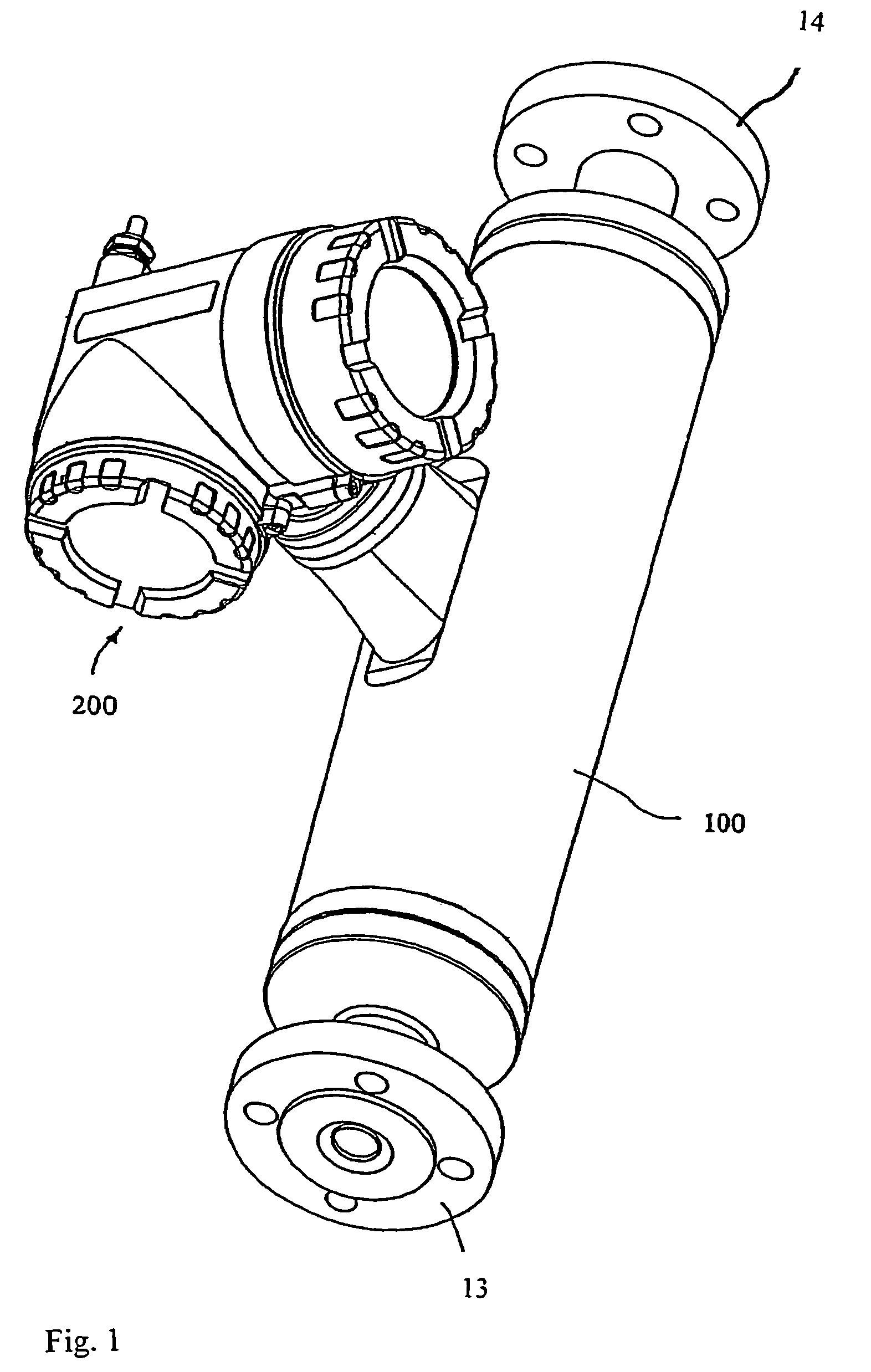
[0060]FIG. 1 is a perspective illustration of a Coriolis mass flow measuring device 1 for registering a mass flow rate m of a medium flowing in a pipeline (not shown) and for reflecting such in the form of a mass flow rate measurement value Xm instantaneously representing this mass flow rate. The medium can be practically any flowable material, for example a liquid, a gas, a vapor, or the like. Moreover, the Coriolis mass flow measurement device 1 can, on occasion, also be used for...


PUM

PropertyMeasurementUnit
oscillation frequencyaaaaaaaaaa
lengthaaaaaaaaaa

Abstract

A Coriolis mass flow measuring device includes a vibratory measuring transducer having at least one measuring tube, which has medium flowing through it during operation. In operation, the measuring tube is caused by an exciter arrangement to undergo mechanical oscillations, especially bending oscillations. Additionally, the Coriolis mass flow measuring device includes a sensor arrangement for producing oscillation measurement signals (s1, s2) representing the inlet-end and outlet-end oscillations of the measuring tube. Measuring device electronics controlling the exciter arrangement produces an exciter current (iexc) and an intermediate value (X′m) derived from the oscillation measurement signals (s1, s2). This intermediate value represents an uncorrected mass flow. Derived from the exciter current and / or from a component of the exciter current (iexc), an intermediate value (X2) is produced, which corresponds to a damping of the oscillations of the measuring tube. This damping is especially a function of an apparent viscosity, and / or a viscosity-density product, of the medium guided in the measuring tube. Furthermore, a correction value (XK) is produced for the intermediate value (X′m) utilizing the intermediate value (X2) and a viscosity measurement value (Xη) determined initially or during operation. The viscosity measurement value (Xη) corresponds to a viscosity of the medium guided in the measuring tube and / or to a predetermined reference viscosity. On the basis of the intermediate value (X′m) and the correction value (XK), the measuring device electronics then produces an exact mass flow rate measurement value (Xm).

Description

[0001]This is a continuation of U.S. application Ser. No. 11 / 084,507 filed on Mar. 21, 2005 now U.S. Pat. No. 7,040,181 which is a nonprovisional of provisional application No. 60 / 556,491 filed on Mar. 26, 2004 and provisional application No. 60 / 570,490 filed on May 13, 2004.FIELD OF THE INVENTION[0002]The invention relates to a Coriolis mass flow / density meter for a medium, particularly a medium of two or more phases, flowing in a pipeline, as well as to a method for producing a measurement value representing mass flow.BACKGROUND OF THE INVENTION[0003]In the technology of process measurements and automation, for the measurement of physical parameters of a medium flowing in a pipeline, parameters such as e.g. mass flow rate, density and / or viscosity, it is common to use such in-line measuring devices, especially Coriolis mass flow measuring devices, which use a vibratory transducer inserted into the course of the pipeline conducting the medium and traversed by the medium during oper...

Claims


Application Information

Patent Timeline
Patent Type & Authority Patents(United States)
IPC IPC(8): G01F1/84G01F15/00G01N9/00G01N11/16
CPCG01F1/8409G01F1/8413G01F1/8418G01F1/8422G01F1/8427G01F1/8431G01F1/8436G01F1/849G01F15/00G01F15/024G01N9/002G01N11/162
Inventor RIEDER, ALFREDDRAHM, WOLFGANGFUCHS, MICHAELSPRICH, HANS-JORGITIN, IBHOWYSS, SAMUEL
Owner ENDRESS HAUSER FLOWTEC AG
Why Eureka
Try Eureka