Filter control apparatus

a filter control and filter technology, applied in combination devices, machines/engines, chemical/physical processes, etc., can solve the problems of reducing the precision of pressure information possessed by the pressure sensor output signal, difficult to estimate accurately the quantity of accumulated particulates on the basis of the before and after, and difficulty in passing exhaust gas through the exhaust gas passage. achieve the effect of more accuracy and high precision

Inactive Publication Date: 2008-04-15
DIESEL KIKI CO LTD
View PDF12 Cites 37 Cited by
  • Summary
  • Abstract
  • Description
  • Claims
  • Application Information

AI Technical Summary

Benefits of technology

[0014]When selecting either of the estimation results of the first and second estimation means, sedimentary particulates can be estimated more accurately by calculating the amount of deviation between the two estimation results, storing the amount of deviation as a learning value and, in accordance with the learning value, correcting calculated values in the second estimation means.
[0019]In accordance with the above configuration, one selected from estimated accumulated particulate quantity value obtained based on the before and after exhaust-gas differential pressure of the filter, and estimated accumulated particulate quantity value calculated from engine operation parameters or the like, is used selectively, taking into consideration the engine operation status and the differential between the two estimation values. The result of this is that it becomes possible to estimate the accumulated particulate quantity with higher precision, making it possible to determine a suitable filter regeneration timing with more accuracy.

Problems solved by technology

Particulates trapped by the filter gradually accumulate and ultimately clog the filter, making it difficult for the exhaust gas to pass through the exhaust gas passage.
However, the above-described conventional technology has the following problem points.
When the engine is operating at a low speed such as when it is idling or the like, the flow rate of the exhaust gas in the exhaust path decreases, which reduces the before and after differential pressure of the filter even when the quantity of accumulated particulates is small, making it difficult to estimate accurately the quantity of the accumulated particulates on the basis of the before and after differential pressure of the filter.
The precision of the pressure information possessed by the pressure sensor output signal therefore declines, and the level of the output signal from the pressure sensor also becomes lower and susceptible to noise, so pressure sensor characteristics problems also make it difficult to accurately estimate the quantity of accumulated particulates.
Furthermore, in cases such as when particulates have accumulated in the filter and the filter continues to be in a high-temperature state when engine operation has been stopped, volatile components released by the accumulated particulates in the filter produces cracking in the particulates.
When such cracking occurs, exhaust gas passes through the cracked portion and inside the filter, reducing the air-flow resistance of the filter.
As a result, the before and after differential pressure of the filter becomes smaller compared to before the occurrence of the cracking, and if in this state the exhaust gas differential pressure is used to estimate the quantity of accumulated particulates, it results in a reduced estimate of the quantity of accumulated particulates, making it difficult to accurately estimate the quantity of accumulated particulates.
As such, in previous apparatuses in which filter regeneration is controlled by measuring the before and after exhaust-gas differential pressure of the filter, regeneration is carried out in a state in which there is a large amount of accumulated particulates in the filter, which risks causing fusing damage to the filter.
Due to the difficulty of accurately estimating the quantity of accumulated particulates, with higher filter regeneration frequency, there are also the problems of deterioration in fuel consumption and shortening of filter life.

Method used


Image

  • Filter control apparatus
  • Filter control apparatus
  • Filter control apparatus

Examples


Embodiment Construction

[0024]In order to explain the present invention in greater detail, it will now be described with reference to the attached drawings.

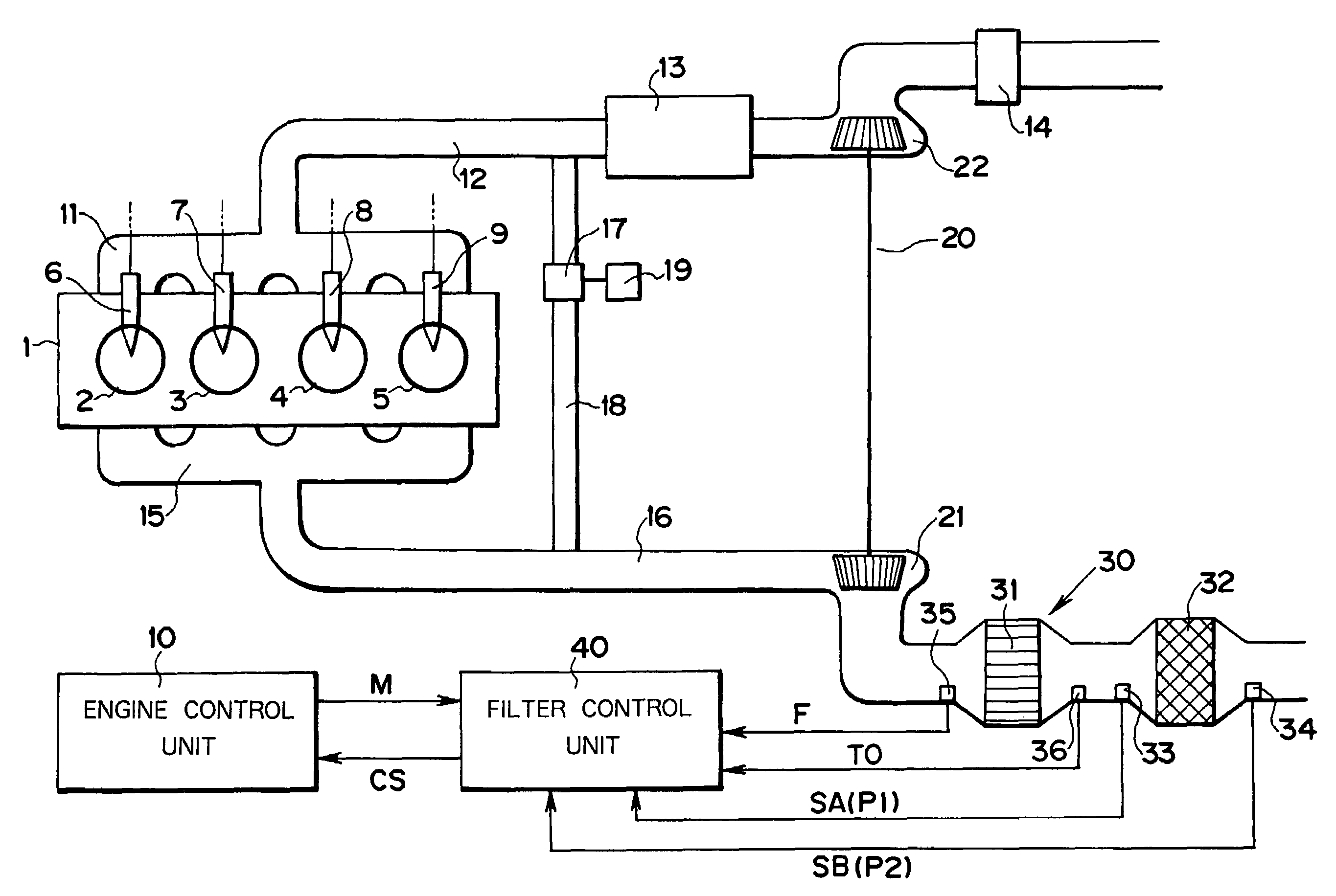
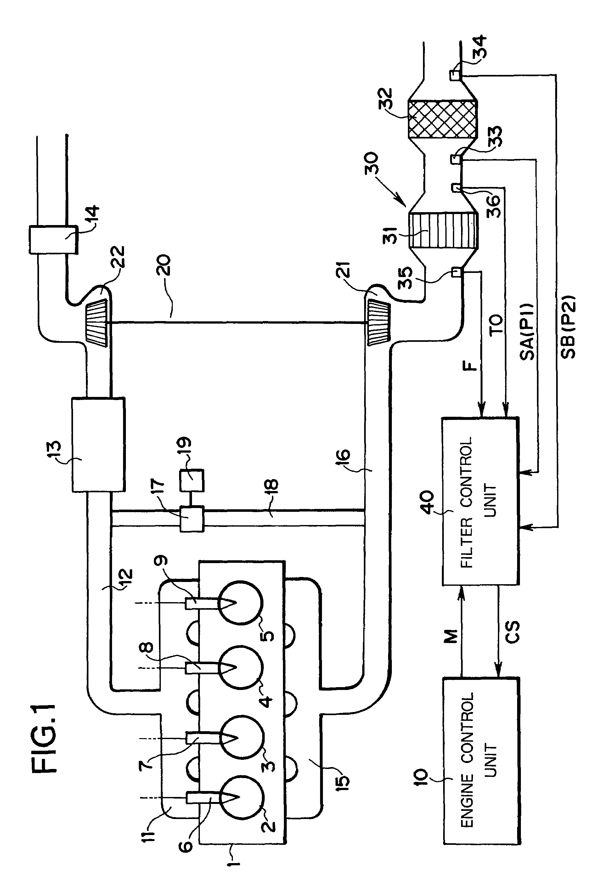
[0025]FIG. 1 is an overall schematic diagram of an example of an embodiment of the present invention showing a case in which filter control is applied to after-treatment of the exhaust gas of a diesel engine. Symbol 1 denotes a four-cylinder diesel engine, the cylinders 2-5 of which are provided with injectors 6-9, respectively. The operation of these injectors 6-9 is controlled by an engine control unit 10, using a known arrangement to inject a required amount of high-pressure fuel, at a required timing, into the corresponding cylinder.

[0026]An intake duct 12 connected to an intake manifold 11 is provided with an inter-cooler 13 and an air cleaner 14. An exhaust duct 16 connected to an exhaust manifold 15 is provided with an exhaust gas after-treatment apparatus 30.

[0027]An exhaust recirculation channel 18 provided with an EGR control valve 17 is provi...


PUM

PropertyMeasurementUnit
exhaust-gas differential pressureaaaaaaaaaa
temperatureaaaaaaaaaa
timeaaaaaaaaaa

Abstract

In order to calculate an estimation of the quantity of accumulated particulates in a filter (32), a first estimation calculation unit (100) that outputs first estimation data (XA) calculated from the filter before and after differential pressure, and a second estimation calculation unit (110) that outputs second estimation data (XB) based on the engine operation status. Of the first and second estimation data (XA, XB), the estimation data having the higher dependability, as viewed from the engine speed at that time, is selected, whether or not to regenerate the filter is determined and with the differential between the first and second estimation (XA, XB) also taken into consideration, when the differential is larger than a prescribed value, even if the engine speed is high, the first estimation data XA is not selected since there is a risk that the dependability of the estimation value is low due to cracking of the accumulated particulates.

Description

TECHNICAL FIELD[0001]The present invention relates to a filter control apparatus capable of regenerating, at a suitable timing, a filter for trapping particulates contained in exhaust gas discharged from an engine.BACKGROUND ART[0002]To suppress the atmospheric diffusion of particles contained in the exhaust gas of diesel engines, in recent years, various apparatuses are being developed for mounting in the exhaust system of diesel engines for after-treatment of diesel particulates in the exhaust gas. Exhaust gas treatment apparatuses of this type all include a filter for trapping particulates contained in the exhaust gas discharged from the diesel engine. Particulates trapped by the filter gradually accumulate and ultimately clog the filter, making it difficult for the exhaust gas to pass through the exhaust gas passage.[0003]Conventionally, therefore, when it is estimated that the quantity of the accumulated particulates in the filter has reached a prescribed level, the filter is h...

Claims


Application Information

Patent Timeline
Patent Type & Authority Patents(United States)
IPC IPC(8): B01D46/00F01N3/023F01N3/021F01N3/022F01N3/035F01N9/00F01N11/00F01N13/02F02B29/04F02B37/00F02D41/02F02M25/07
CPCF01N13/009F01N9/002F01N9/005F02D41/029F02D41/1448F01N3/0212F01N3/035F01N2250/02F01N2330/06F01N2530/04F01N2550/04F01N2900/0402F01N2900/0412F01N2900/0418F01N2900/08F01N2900/1406F01N2900/1606F02B29/0406F02B37/00F02D2200/0812F02M25/0707Y02T10/47Y10S55/30Y10S55/10F01N3/0222F02M26/05Y02T10/40F01N9/00
Inventor HAMAHATA, TOSHIHIROWATANABE, TOMONORI
Owner DIESEL KIKI CO LTD
Why Eureka
Try Eureka