
Apparatus and catalytic partial oxidation process for recovering sulfur from an H2S-containing gas stream

a technology of partial oxidation and apparatus, which is applied in the direction of separation process, sulfur preparation/purification, lighting and heating apparatus, etc., can solve the problem that the conventional claus plant cannot handle such large amounts of hsub>2/sub>s, and achieve the effect of less costly sulfur recovery plant and process, short contact time and expansion of claus plant capacity

Inactive Publication Date: 2008-04-15
PHILLIPS 66 CO
View PDF82 Cites 9 Cited by
  • Summary
  • Abstract
  • Description
  • Claims
  • Application Information

AI Technical Summary

Benefits of technology

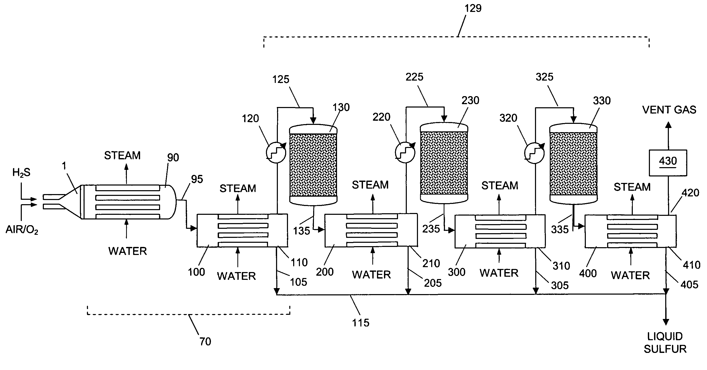
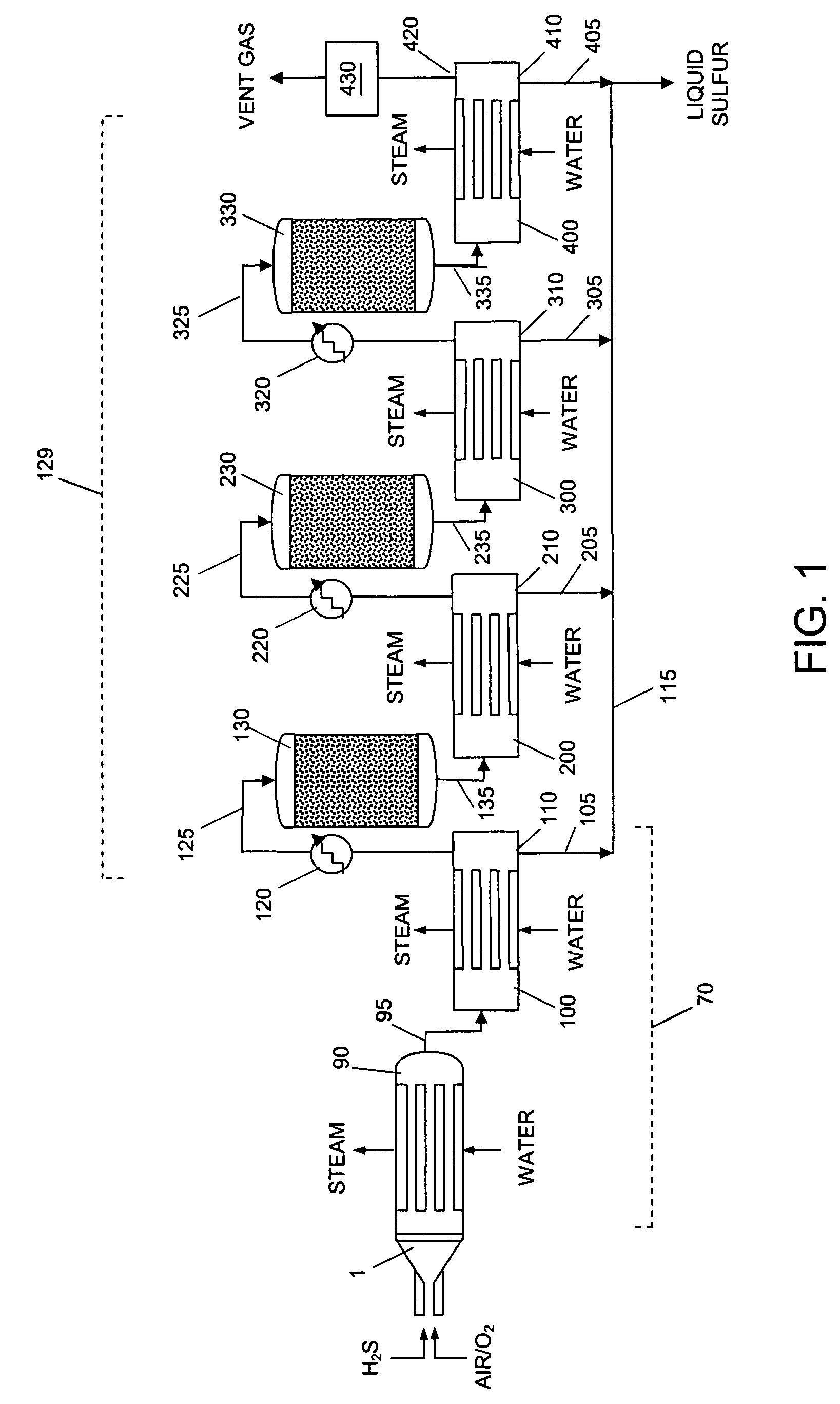
[0021]The various embodiments of the present invention solve many of the operational drawbacks of existing Claus plants and sulfur recovery processes by replacing the customary Claus burner and reaction furnace with a more efficient short contact time catalytic partial oxidation reactor (SCTR) and H2S partial oxidation catalyst capable of operating efficiently at higher temperatures than has been previously thought possible or practical. Thus, a simpler, less costly sulfur recovery plant and process are provided. Expansion of Claus plant capacity is made possible using smaller, less complicated equipment. A sulfur recovery process using the disclosed apparatus avoids formation of the problem by-products that are typical of most Claus processes used today. Some of the present or potential advantages offered by the present methods and apparatus include: a) the ability to efficiently process feeds containing as little as about 10% H2S and up to about 100% H2S; b) elimination of undesirable products of hydrocarbon combustion from the product gas stream; c) by eliminating the Claus furnace, the problem of lowered flame temperature due to excessive carbon dioxide (CO2) in the feed gas is avoided; d) ammonia in the feed gas is decomposed by the SPOC™ catalyst instead of reacting with SO2 in the reaction furnace; e) the problems associated with insufficient residence time in the Claus burner / reaction furnace are avoided; and f) excessive pressure drop caused by flow friction in conventional Claus furnaces is reduced.
[0022]By substituting the present apparatus and process for a conventional Claus plant and process, the processing of greater amounts of sour crude oil and sour natural gas in petroleum refineries is made possible. The handling of such large amounts of H2S would be impossible using conventional Claus plants. By substituting a sulfur removal system of the present invention for a conventional Claus burner, a sulfur recovery plant can be economically modified to handle higher capacities and a wider range of operations than would be possible with a conventional Claus burner.
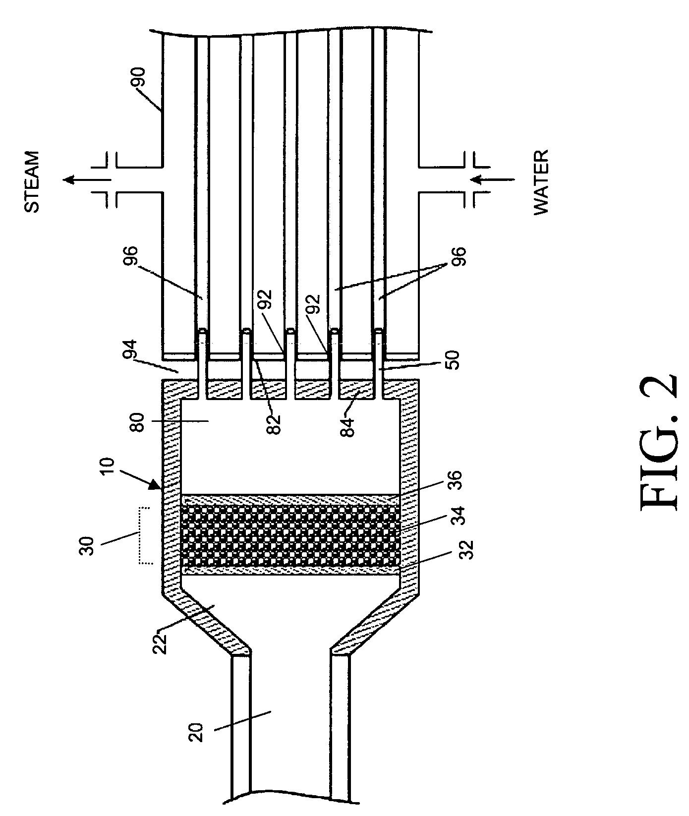
[0023]The present process also provides an improvement over other catalytic direct oxidation methods for converting H2S directly to sulfur by eliminating the need to limit the operating temperature to less than 500° C., and avoiding the need for a large stoichiometric excess amount of O2—Without wishing to be limited to a particular theory, it is thought that the temperature constraints that are typical of existing (low temperature) direct oxidation processes are avoided in the present SPOC™ process, which is operated at elevated temperature, due to the use of efficient and selective partial oxidation catalysts, high flow rates (short residence time on the hot catalyst), and rapid quenching of the reacted gases (i.e., less than 100 milliseconds), which minimizes the occurrence of undesirable side reactions such as the reverse Claus reaction and recombination of hydrogen and sulfur to make H2S. Thus, a SPOC™ reactor system can provide equivalent or better yield of elemental sulfur than a Claus burner / reactor furnace unit. The new process, and system for carrying out such process, are capable of operating at gas hourly space velocities (GHSV) above 20,000 h−1. In some embodiments the GHSV is above 100,000 h−1. In some embodiments the preferred GHSV is in the range of 500,000 h−1 to 1,000,000 h−1. The new process and system is preferably capable of providing high conversion levels of H2S and high selectivity for elemental sulfur production. These improvements provide a much simpler sulfur processing unit which can be incorporated in line with most petroleum refinery or natural gas plants such as hydrotreaters, cokers, and fluid catalytic crackers. The process of the present invention employs catalysts that are active for catalyzing the direct partial oxidation of H2S to sulfur and water in a short contact time reactor (SCTR) at elevated temperatures that exceed the useful operating temperatures of known direct oxidation processes. For the purposes of this disclosure the term “elevated temperature,” when used in the context of the catalyst, process and SCTR of the present invention, refers to a temperature or range of temperatures above 500° C., preferably in the range of 550-1,500° C., more preferably in the range of 800-1,450° C. In certain embodiments of the present invention, a conventional Claus sulfur recovery plant, which normally has a combustion furnace for combusting hydrogen sulfide to form elemental sulfur and water, is improved by replacing the combustion burner or furnace with a flameless millisecond contact time catalytic reactor, sometimes referred to herein as a SPOC™ reactor.
[0032]An advantage provided by certain embodiments of the present invention is that existing processes for removing H2S from an H2S-containing gaseous stream that customarily employ a Claus sulfur recovery plant with a first stage burner / reactor furnace in which H2S is combusted and reacted with formed SO2, and at least one second stage catalytic reactor in which H2S and SO2 are converted to elemental sulfur and water, is that such plants can be improved by substituting a flameless millisecond contact time catalytic reactor for the Claus first stage furnace.

Problems solved by technology

The handling of such large amounts of H2S would be impossible using conventional Claus plants.

Method used


Image

  • Apparatus and catalytic partial oxidation process for recovering sulfur from an H<sub>2</sub>S-containing gas stream
  • Apparatus and catalytic partial oxidation process for recovering sulfur from an H<sub>2</sub>S-containing gas stream
  • Apparatus and catalytic partial oxidation process for recovering sulfur from an H<sub>2</sub>S-containing gas stream

Examples


example 1

SPOC™ Resolves the Problem of Hydrocarbon Contamination of the H2S Feed

[0062]The typical problems caused by hydrocarbon contamination of the H2S feed are greatly improved or entirely avoided by the present process. The standard Claus burner / combustion stage is improved upon by only partially oxidizing the hydrocarbon components of the H2S feed instead of fully combusting them. Full or complete combustion can be described by the reaction

CmHn+(m+n / 4)O2→mCO2+n / 2H2O  (7)

whereas partial oxidation of a hydrocarbon can be described by the reaction

CmHn+(a+b / 2+d / 2)O2.aCO2+bCO+cH2+dH2O+(m−a−b)CmHn  (8)

For partial oxidation, (a+b / 2+d / 2)<(m+n / 4).

[0063]The effect of including methane in the H2S feed was determined as follows: The laboratory scale SPOC™ reactions were carried out in a modified conventional flow apparatus using a quartz reactor with a length of 12 inches, an outside diameter of 19 mm and an inside diameter of 13 mm. Ceramic foam pieces of 99% Al2O3 (12 mm outside diameter×5 mm thi...

example 2

SPOC™ Resolves the Problem of Excessive CO2 in the H2S Feed

[0070]The test procedure described in Example 1 was employed, except methane was omitted from the H2S feed and CO2 was included in the amounts indicated in Table 3. The test data in Table 3 shows the conversions attained using the present invention with varying levels of CO2 in the feed, normally classified as “lean” feeds for a Claus plant. These reaction yields were attained with stable reaction conditions that did not include fuel gas addition or equipment to split the flow of H2S, in contrast to typical Claus processes in which excessive CO2 is present in the feed.

[0071]

TABLE 3Straight-through Conversion of Low Levels of H2S to Sulfur% H2S Flow% CO2 in Feed% Sulfur Yield33.7566.2567.028.9671.0466.225.3674.6466.622.5577.4566.7

example 3

SPOC™ Process Destroys Ammonia in the Feed

[0072]The same test procedure described in Example 1 was employed, except methane was omitted from the H2S feed and NH3 was included in the amount indicated in Table 4. The catalyst was composed of 2% Pt-1% Rh / 2% Mg on magnesium oxide granules, and formed a ¾″ L×½″ D bed. The test results in Table 4 show the NH3 destruction performance under the indicated conditions. It can also be appreciated that the SPOC™-modified Claus process provides an advantage over conventional Claus processes in reduced residence time.

[0073]

TABLE 4Inlet NH3NH3concentrationResidenceconversionAirH2SNH3Air / (%)Time (msec)(%)(SLPM)(SLPM)(SLPM)(H2S + NH3)H2S / NH314.10738.483.322.6520.9620.1582.376.114.10737.387.692.7630.9620.1582.476.114.12036.393.922.8730.9610.1582.576.114.12035.397.632.9860.9610.1582.676.114.12034.497.973.0950.9610.1582.776.114.10733.598.693.2060.9620.1582.866.114.12032.698.823.3190.9610.1582.976.1

[0074]As demonstrated above, a preferred SPOC™ catalyst ...


PUM

PropertyMeasurementUnit
temperatureaaaaaaaaaa
contact timeaaaaaaaaaa

Abstract

The disclosed sulfur recovery system and process avoid some of the operational problems of conventional Claus plants and processes by replacing the reaction burner and furnace tube of a conventional Claus plant with a more efficient short contact time catalytic reactor assembly containing a SPOC™ catalyst that operates efficiently at elevated temperatures. Such Claus plant modification also reduces or avoids the negative effects of hydrocarbons, CO2 and ammonia in Claus sulfur plant feeds, and permits efficient processing of dilute to concentrated H2S feeds. The disclosed modification makes possible the expansion of Claus plant capacity at lower cost.

Description

CROSS-REFERENCE TO RELATED APPLICATIONS[0001]This application is a continuation-in-part of U.S. patent application Ser. No. 10 / 024,679 filed Dec. 18, 2001, now U.S. Pat. No. 6,946,111, which claims the benefit under 35 U.S.C. § 119(e) of U.S. Provisional Patent Application No. 60 / 256,440 filed Dec. 18, 2000. The disclosure of each said application is hereby incorporated herein by reference.BACKGROUND OF THE INVENTION[0002]1. Technical Field of the Invention[0003]The present invention generally relates to Claus sulfur recovery plants and to processes for recovering sulfur from H2S-containing gas streams. More particularly, the invention relates to a Claus process and apparatus in which the combustion stage is replaced by a catalytic partial oxidation stage in which elemental sulfur and sulfur dioxide is produced.[0004]2. Description of the Related Art[0005]Sulfur-recovery plants, also called Claus plants, are well known for removing hydrogen sulfide gas (H2S) resulting from petroleum...

Claims


Application Information

Patent Timeline
Patent Type & Authority Patents(United States)
IPC IPC(8): C01B17/04B01D53/86
CPCB01D53/8612B01D53/8693C01B17/0404C01B17/0417C01B17/046C01B2203/1241C01B2203/127C01B2203/1282
Inventor RAMANI, SRIRAMKELLER, ALFRED E.
Owner PHILLIPS 66 CO
Learn More