Electromagnetic inductive system with multi-induction loop layout and battery less pointer device and its method for locating the coordinate

Active Publication Date: 2008-04-15
WACOM CO LTD
View PDF20 Cites 0 Cited by
  • Summary
  • Abstract
  • Description
  • Claims
  • Application Information

AI Technical Summary

Benefits of technology

[0009]In view of the prior art, focusing on the enhancement and to increase the function of the inductive loops of the conventional electromagnetic inductive system. The present invention provides a multi-induction loop layout of an electromagnetic inductive system with a battery-less pointer device (a pen, a mouse, a locating plate, etc.) and its method for calculating the coordinates, which is able to eliminate the said defect of the conventional electromagnetic inductive system.
[0010]One main purpose of the invention is to provide an electromagnetic inductive system with a battery-less pointer device and the multi-induction loops layout and its method for calculating the coordinates. The invention processes a procedure of calculating the coordinates through a battery-less pointer device and a multi-induction loop layout. Besides, the battery-less pointer device of the invention is consisted of a variable inductance element. When the inductance changes, the resonant frequency also changes, and therefore the frequency of the electromagnetic signal induced by the inductive loops also different. With this multi-induction loops layout, the invention can reduce the space demand of the electromagnetic inductive system and the size of its PCB (whether it is a inflexible or flexible PCB is not confined here). Thus the goal of minimizing the space bounded and the product appearance, reducing production costs, and intensifying the efficiency of the electromagnetic inductive system is achieved. Therefore, the invention fits in with economic benefit and industrial practicability.

Problems solved by technology

However, without careful handling, the change in frequency and phase could easily cause misjudgment in the desired function of the pointer device because of various external factors such as metallic objects, noise signals, exterior electromagnetic fields, etc.
These problems become extraordinarily obvious when it comes to tablets of larger size.
However, as far as a tablet of a larger size is concerned, the number of inductive loops arranged also increases, and therefore more loop switches are needed.
But as the speed of processing and data rate increase, the phenomenon of electromagnetic interference will happened often.
Therefore the conventional tablet is easily interfered with by exterior electromagnetic fields and thus misjudgment is a result.
This limits the miniaturization of a PCB for a handwriting tablet and makes it difficult to design and produce a tablet with the small boundary.

Method used


Image

  • Electromagnetic inductive system with multi-induction loop layout and battery less pointer device and its method for locating the coordinate
  • Electromagnetic inductive system with multi-induction loop layout and battery less pointer device and its method for locating the coordinate
  • Electromagnetic inductive system with multi-induction loop layout and battery less pointer device and its method for locating the coordinate

Examples


first embodiment

[0021]Referring to FIG. 2, in the present invention, a multi-induction loop 200 is provided, one end of which being electrically coupled with a loop switch 210, and the other end of which being electrically coupled with a common node 220. The multi-induction loop 200 comprises a plurality of -type sections. For example, the first -type section 230A, the second -type section 230B, the third -type section 230C, the fourth -type section 240A, the fifth -type section 240B, and the sixth -type section 240C. The a plurality of -type sections 230A to 230C are composed of the first sawtooth-shaped region 260A. The a plurality of -type sections 240A to 240C are composed of a second sawtooth-shaped region 260B. The second sawtooth-shaped region 260B and the first sawtooth-shaped region 260A make up a relative close inductive loop. From each -type section 230A to 230C and each -type section 240A to 240C; opposite each other, form the relatively close-like regions 250A to 250C. The multi-induct...

second embodiment

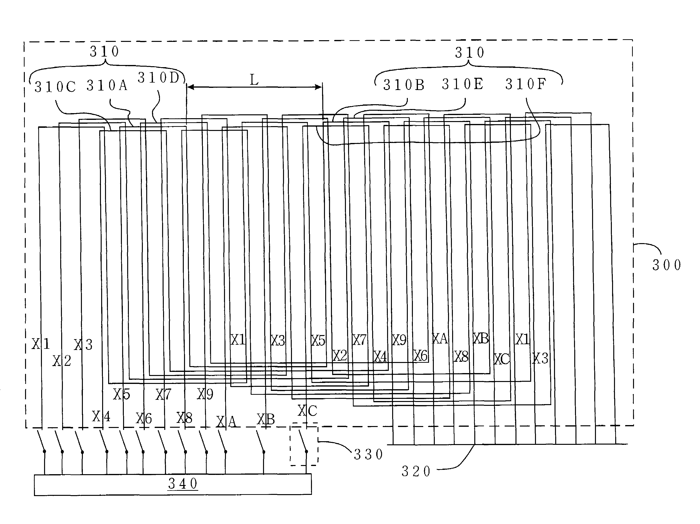
[0022]Referring to FIG. 3, in the invention, a multi-induction loop layout 300 (only the x axis of which is indicated) with a plurality of physical inductive loops (X1-X9 and XA-XC) is provided. Each physical inductive loop (from X1 to X9 and from XA to XC) is being deployed along the X axis of the orthogonal two-dimensional coordinates and composed by a plurality of logical inductive loops 310, which are essentially consistent -type sections. Each multi-induction loop (from X1 to X9 and from XA to XC) is electrically coupled with a corresponding loop switch 330, and the other terminal of the loop is electrically coupled with a common node 320. As far as the deployment of each multiple physical inductive loop in the same direction is concerned, each logical inductive loop 310 and other adjacent logical inductive loops, specifically correspond to a respective physical inductive loop (X1-X9 and XA-XC). Therefore, a specific logical inductive loop on which the pointer device is located...

third embodiment

[0023]Referring to FIG. 4A, in the invention, an electromagnetic inductive system 400A is provided. The pointer device, which is a battery-less pointer device 400B, has an electromagnetic inductive storage circuit that comprises a variable inductor. The electromagnetic inductive system 400A comprises a set of loops sub-circuit 405, an interior circuit 410, and a microprocessor sub-circuit 415. The interior circuit 410 comprising a filter and amplifier sub-circuit 420, a pre-amplifier sub-circuit 425, a waveform generating sub-circuit 430, and a frequency-to-voltage converter sub-circuit 435, and the loops sub-circuit 405 comprising a multi-inductive loop layout 440 and a group of the loop switches 445. The multi-inductive loop layout 440 comprises a plurality of physical inductive loops 450 that are electrically coupled respectively with a plurality of bi-direction loop switches 445A of the loop switch group 445, which is electrically coupled with the pre-amplifier sub-circuit 425 a...


PUM


Abstract

A multi-induction loop layout of an electromagnetic inductive system is disclosed. The multi-induction loop layout of the invention comprises a plurality of inductive loops, one terminal of each inductive loop connecting to a loop switch, and the other terminal connecting to the common node. Every logical inductive loop is a relative close inductive loop, the relative close inductive loop possessing a plurality of -type sections, forming a sawtooth-shaped region and corresponding to and closing each other to form a plurality of close-like regions. The form of which gradually approaches the multi-induction loop layout.

Description

BACKGROUND OF THE INVENTION[0001]1. Field of the Invention[0002]The present invention generally relates to a multi-induction loop layout of an electromagnetic inductive system, and more particularly to a method for locating the coordinates of the multi-induction loop layout of an electromagnetic inductive system.[0003]2. Description of the Prior Art[0004]Since a handwriting input device can replace a mouse and allow users to input words and pictures by hand, more easily than a mouse, the field of improvement of a handwriting input device has developed rapidly in recent years. The early handwriting input device replaces a mouse with a pen. In order to increase the convenience of operation for the user, a cordless pointer device, such as a pen, a mouse, a puck or a stylus with a digitizer tablet is usually used. The tip of the cordless pen or stylus corresponds with the left key of the mouse. Although conventional pen-input products have existed for several years, similar kinds of pro...

Claims


Application Information

Patent Timeline
IPC IPC(8): G06F3/041G06F3/033G06F3/044G06F3/045G06F3/046
CPCG06F3/046
Inventor CHAO, CHING-CHUANHSU, CHUNG-WEN
Owner WACOM CO LTD
Why Eureka
Try Eureka