
Method and device for automatically attributing addresses to a plurality of modules interconnected by a communication network with complex topology

a communication network and topology technology, applied in the field of automatic allocation of addresses to a plurality of modules interconnected by a communication network with an arborescent topology, can solve the problems of large number of problems affecting the accuracy of significant errors, and inability to know the exact topology of the network, so as to facilitate the connection of a new module

Inactive Publication Date: 2008-04-15
EDELCOM
View PDF9 Cites 4 Cited by
  • Summary
  • Abstract
  • Description
  • Claims
  • Application Information

AI Technical Summary

Benefits of technology

[0018]By means of these arrangements, the invention exploits the attenuation which occurs in transmissions by carrier current so as to define a delay time whose period depends on the distance between the transmitting module and the receiving module, this delay time being triggered so as to decide which module needs to be allocated with the transmitted address. In this way, the module which is allocated with the transmitted address is the one which has the shortest delay time and thus the one closest to the transmitting module of the message. The invention also makes it possible to by degrees fully automatically allocate a respective address to all the modules of a given branch of the network connected to the central unit without involving any risk of error.
[0019]By repeating this operation for all the branches of the network, it is possible to fully automatically allocate an address to all the modules connected to the network.
[0021]According to one characteristic of the invention, the address of a given module includes an order number obtained by successively numbering all the modules situated on a path directly connecting the given module to the central unit by starting by one for the first module connected on the path to the central unit, as well as one linking address for determining the various line sections constituting the path connecting the module to the central unit. As a result, if all the allocated addresses are retransmitted to the central unit, the list of the allocated addresses makes it possible to restore the topology of the network.
[0028]It is possible to provide a message transmitted by the central unit for initialising the module addresses stored by all or part of the modules connected to the network so as to be able to then allocate new addresses to the reinitialised modules. In this way, it is possible to easily take into account the connection of a new module between two modules already configured.

Problems solved by technology

In addition, the knowledge of the exact topology of the network has quite often disappeared, said network generally resulting from operations of successive installations carried out over several tens of years.
In the context of a network of this types the allocation of an address to each module poses a large number of problems.
Next, if it is desired to interconnect a large number of modules, the addressing of the various modules must be able to be carried out with fastidious handlings which might result in significant risks of error.
Furthermore, the range of transmissions by carrier current is relatively small.
Thus, this method does have the drawback of requiring the intervention of operators on the terrain concerned, said operators needing to take action on the control buttons provided on each module.
In addition, these modules can be only accessed with difficulty as for example they may be installed several meters from the ground at the top of urban lamp posts.
Furthermore, this method is not able to fully eliminate any risk of error as it is possible to initiate the allocation of an address of a module not immediately situated downstream of a module having an address.

Method used


Image

  • Method and device for automatically attributing addresses to a plurality of modules interconnected by a communication network with complex topology
  • Method and device for automatically attributing addresses to a plurality of modules interconnected by a communication network with complex topology
  • Method and device for automatically attributing addresses to a plurality of modules interconnected by a communication network with complex topology

Examples


Embodiment Construction

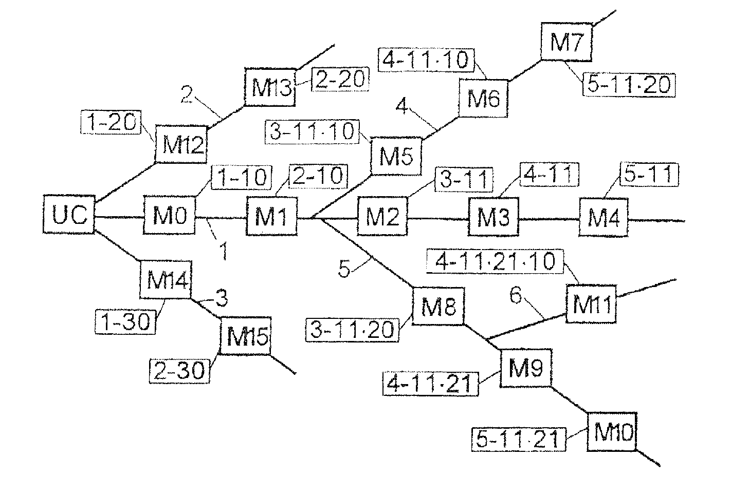
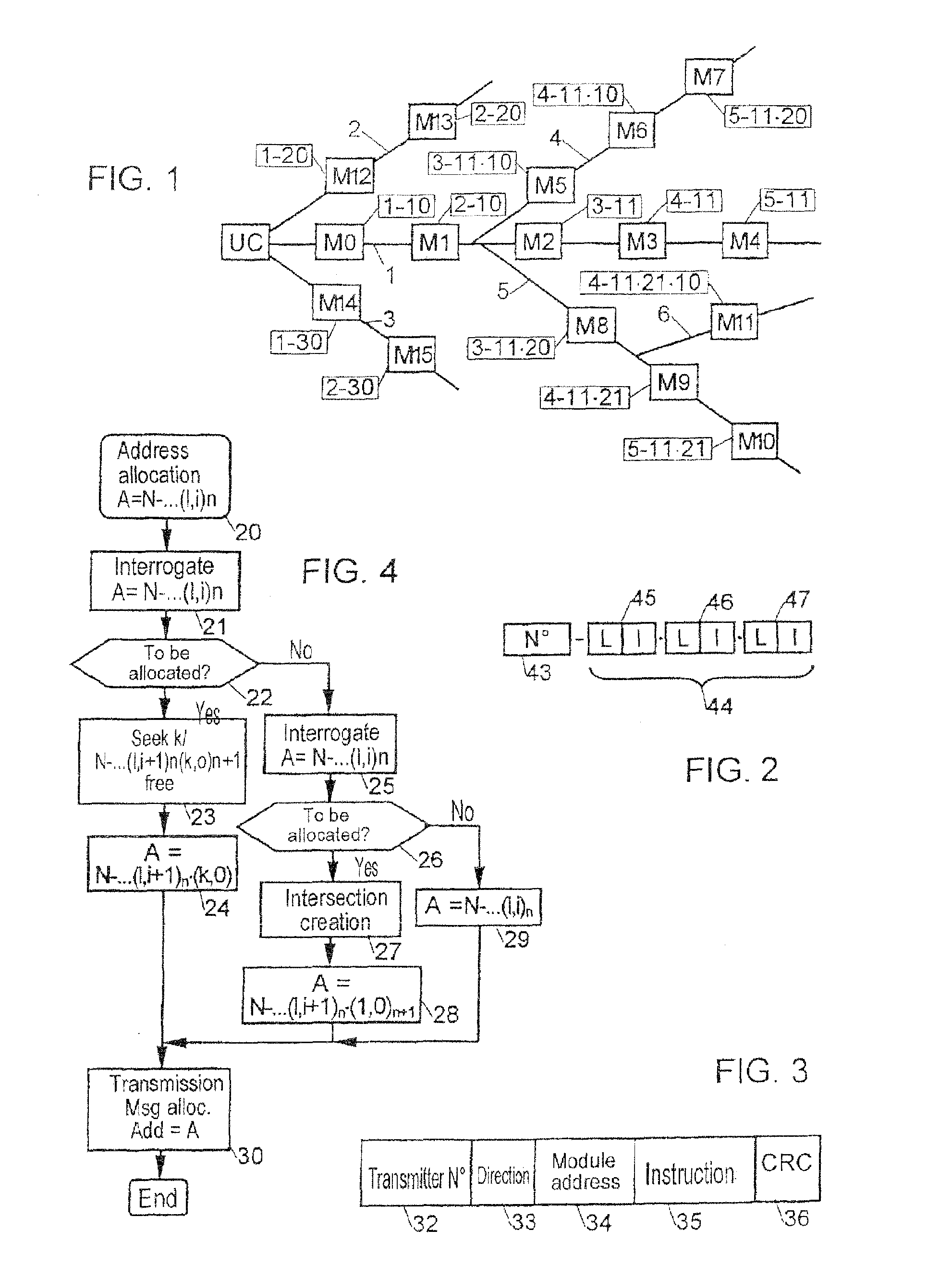
[0039]FIG. 1 represents a star network making it possible to connect a central unit UC to a plurality of electronic modules M1 to M15, the various elements connected by the network communicating with one another by messages, for example transmitted on the network, via the modulation of a carrier wave.

[0040]In this network, the method of the invention seeks to automatically allocate a respective single address to each module according to the position of the latter in the network. To this effect, the invention exploits the attenuation phenomenon according to the distance which occurs, especially when a signal is transmitted on an electric energy feed line. In this case, the transmissions by the network are preferably carried out by a bidirectional carrier current via the phase modulation of a carrier wave.

[0041]Each module Mi connected to the network is marked with respect to the central unit UC by an address constituted by an order number 43 and a linking address 44 (FIG. 2).

[0042]Th...


PUM


Abstract

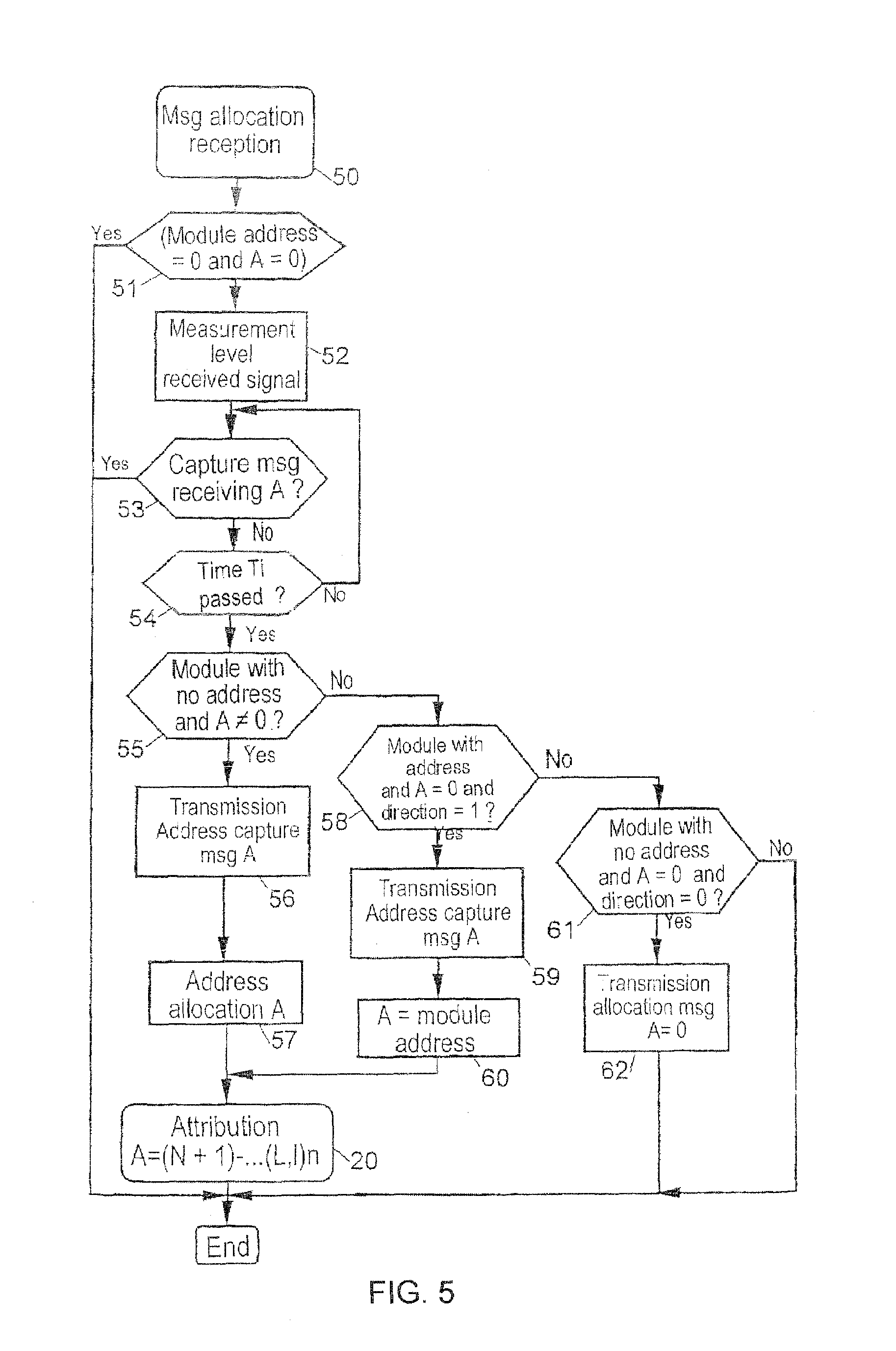
The invention concerns a method whereby each module is determined from the address of the module located immediately upstream in the networked relative to the central unit, the detected address being transmitted by the upstream module in an attribution message, which triggers off an automatic search phase for the module without address, nearest downstream to a module with an address, during which each downstream module without address receives (50) the address attribution message, triggers (52) a delay whereof the duration is so much longer if the received message reception is low, and if at the end (54) of the delay, no address capture message is detected (53), it transmits (56) such a message, stores (57) the received address, determines the address of the nearest downstream module without address, and triggers (30) the search phase for the nearest downstream module without address.

Description

BACKGROUND OF THE INVENTION[0001]1. Field of the Invention[0002]The present invention concerns a method and device for the automatic allocation of addresses to a plurality of modules interconnected by a communication network with an arborescent topology.[0003]It applies in particular, but not exclusively, to a plurality of modules interconnected by an electric distribution network used both for the electric feeding of the modules and as a communication network for the transmission of digital messages between modules via a modulated carrier current.[0004]It is applicable in particular to the remote control and monitoring of urban lamp posts.[0005]2. Description of the Prior Art[0006]It has been observed that an electric distribution network generally has a complex topology comprising a large number of intersections distributed randomly. In addition, the knowledge of the exact topology of the network has quite often disappeared, said network generally resulting from operations of succ...

Claims


Application Information

Patent Timeline
Patent Type & Authority Patents(United States)
IPC IPC(8): H04L12/28H04L29/12H04L12/44
CPCH04L29/12254H04L29/12264H04L61/2038H04L61/2046H04L61/5046H04L61/5038
Inventor DURANTON, RENE
Owner EDELCOM
Learn More