

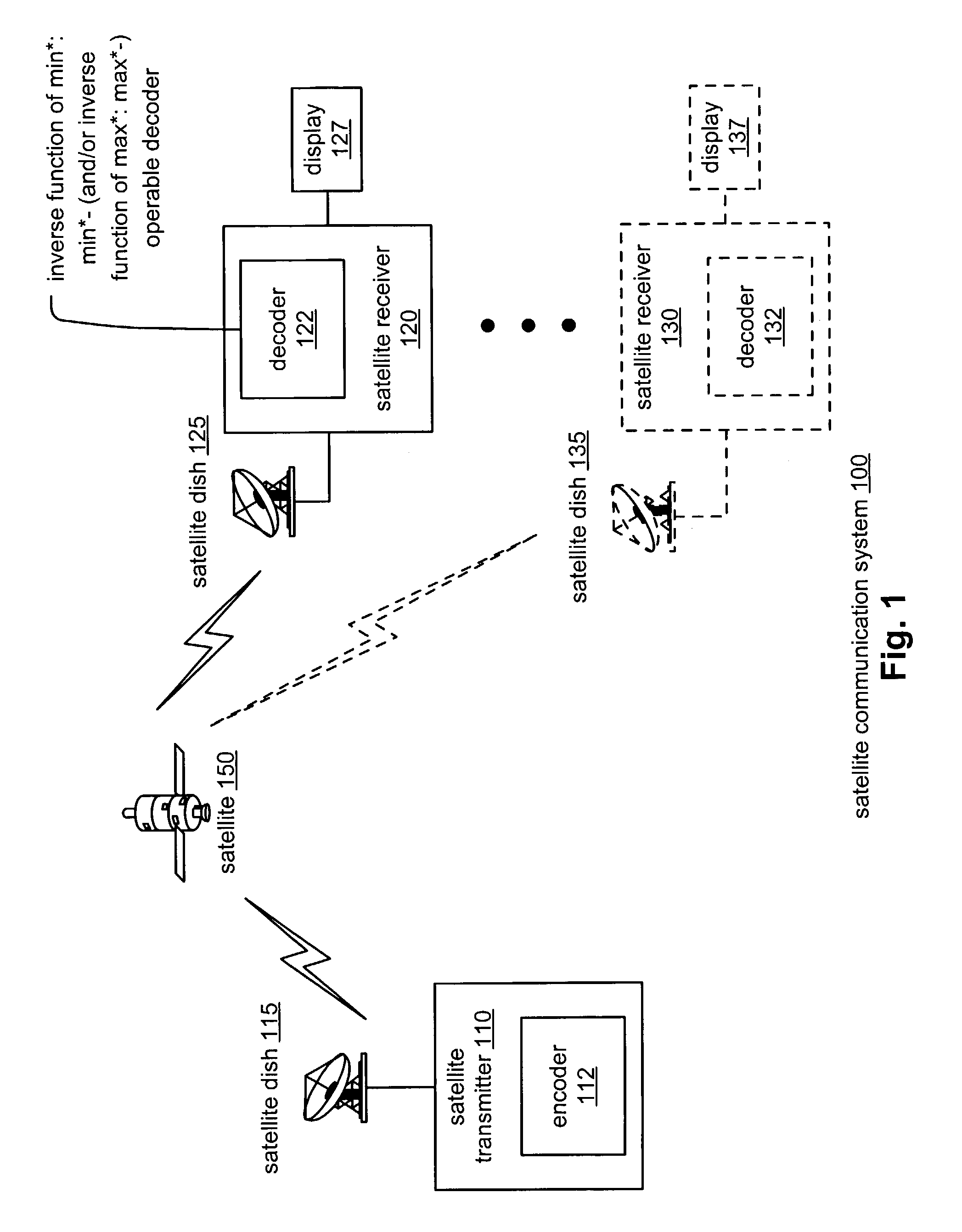
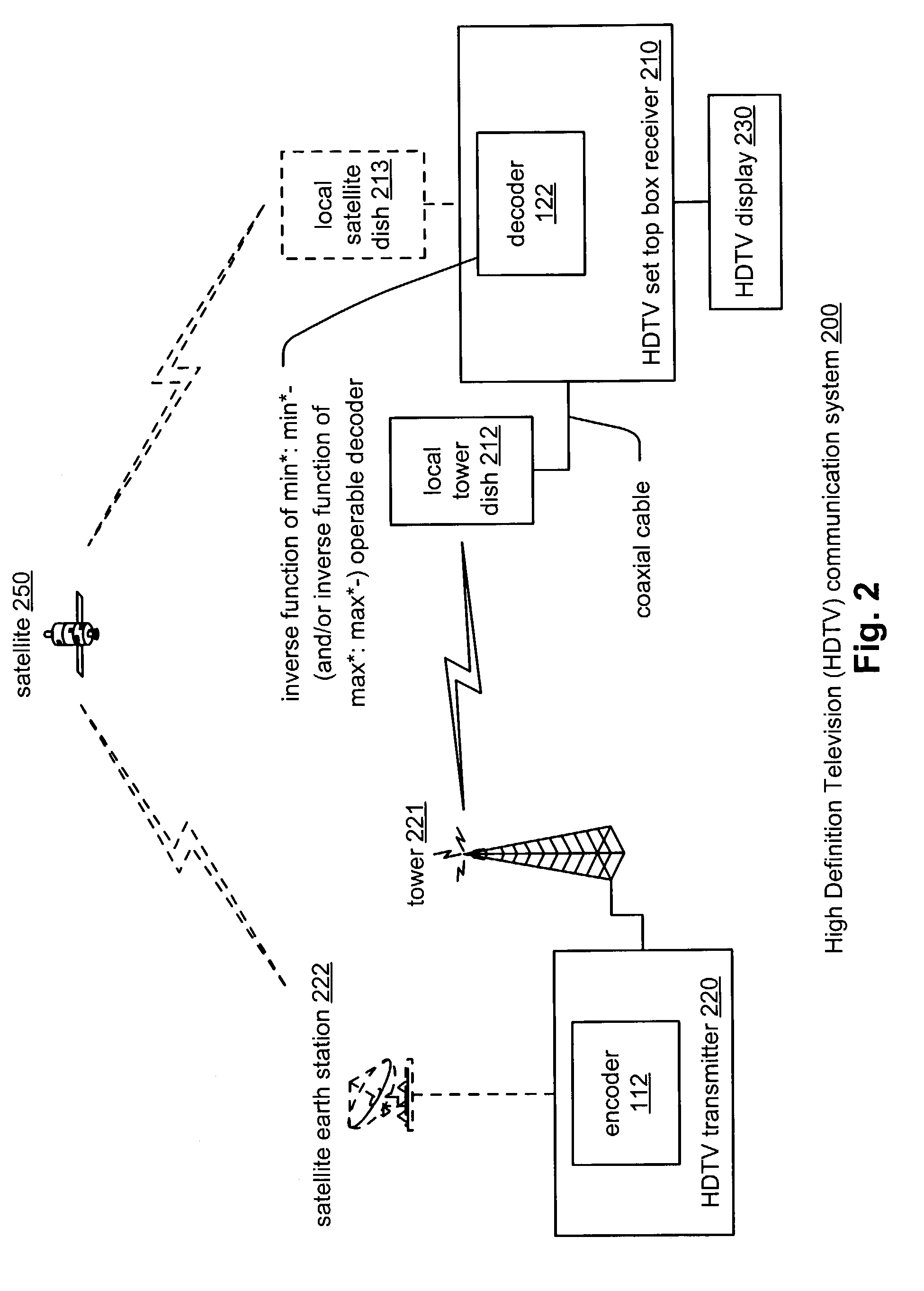
Inverse function of min*:min*- (inverse function of max*:max*-)
a technology of inverse function and inverse function, applied in the field of communication systems, can solve the problems of prohibiting their implementation within systems with very tight design budgets, complex and burdensome computations required to perform decoding, and the total number of processing steps employed in decoding signals is significantly reduced
- Summary
- Abstract
- Description
- Claims
- Application Information
AI Technical Summary
Benefits of technology
Problems solved by technology
Method used
Image

Examples
Embodiment Construction
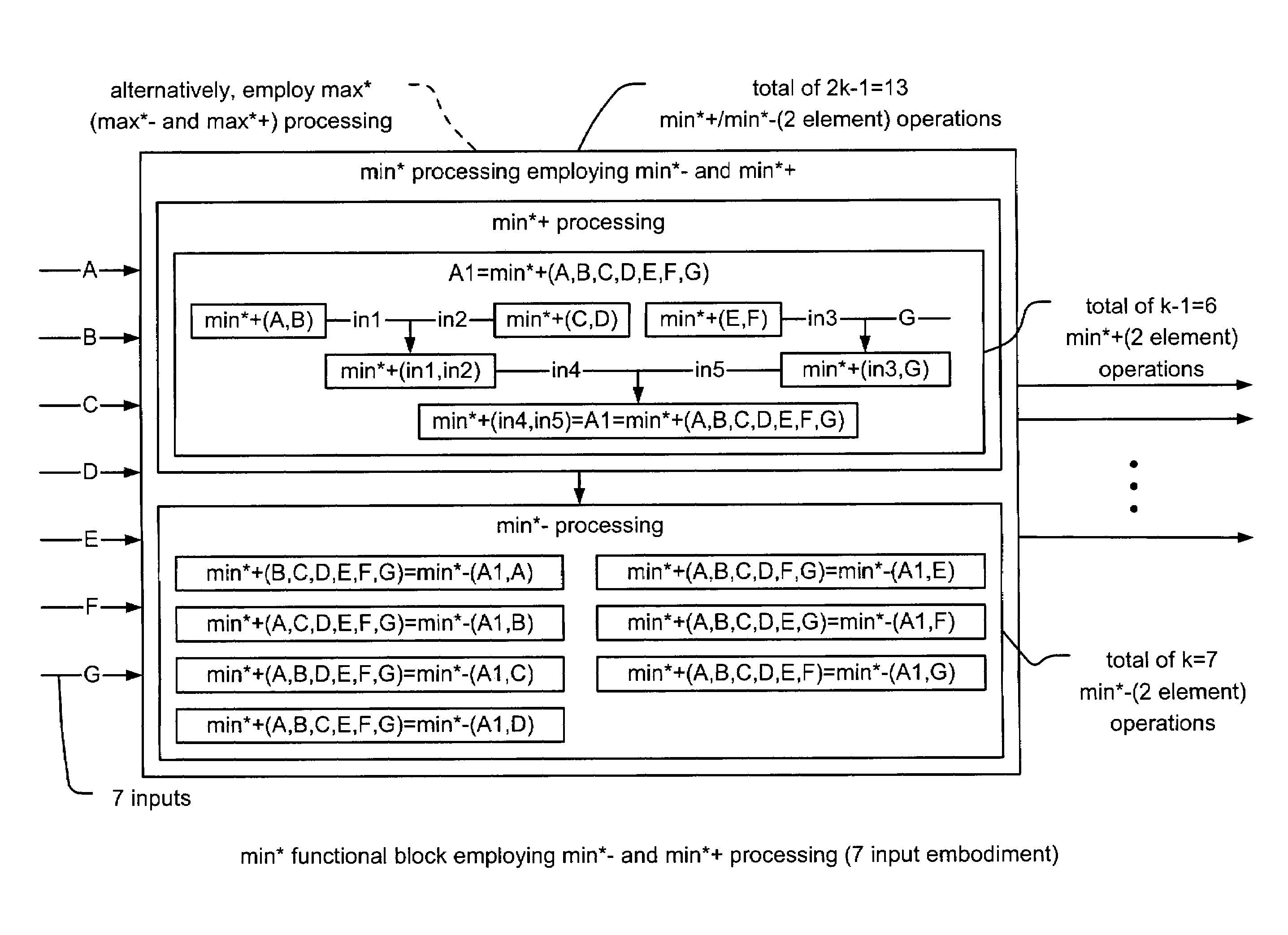
[0047]The decoding process of the invention may properly be described as being performed within a variety of communication systems including those that employ turbo coding, parallel concatenated trellis coded modulated (PC-TCM) code, turbo trellis coded modulated (TTCM) code, low density parity check (LDPC) code, and other codes that perform calculations that are used to identify a minimum (or maximum) value from among a number of possible values during decoding. The invention is operable to perform calculations within the context of max* and / or min* that are used to identify an appropriate selection of a parameter employed within the decoding. The min* or max* calculation may be used when calculating alpha, beta, and extrinsic values, for example in the context of performing turbo related decoding. Any other calculations that seek to identify a minimal or maximal value from among a number of potential values may benefit from the improved computational efficiency and speed of the de...
PUM
 Abstract
Description
Claims
Application Information