Cuff volumetric pulse wave obtaining apparatus, cuff volumetric pulse wave analyzing apparatus, pressure pulse wave obtaining apparatus, and pressure pulse wave analyzing apparatus

Active Publication Date: 2008-04-22
FUKUDA DENSHI CO LTD
View PDF21 Cites 27 Cited by
  • Summary
  • Abstract
  • Description
  • Claims
  • Application Information

AI Technical Summary

Benefits of technology

[0023]According to the eighth aspect of the present invention, after the inverse transfer function corresponding to the transfer function between input, i.e., pressure pulsation produced in the artery and output, i.e., pressure pulsation detected by the pressure sensor, is determined, and is stored by the inverse transfer function memory, the pressure pulse wave produced in the artery is determined, using the inverse transfer function stored by the inverse transfer function memory, based on the actual pressure pulse wave detected by the pressure sensor. The thus determined pressure pulse wave has substantially no distortion and enjoys high accuracy. In addition, the accurate pressure pulse wave is analyzed to determine at least one of the blood pressure, the pulse wave propagation velocity, the arteriosclerosis evaluation index, and the autonomic nerve evaluation

Problems solved by technology

Therefore, when the pulse wave propagates through air in the cuff or the rubber tube that has a great compliance, the waveform of the pulse wave is distorted.
Thus, the extracted cuff volumetric pulse wave may not be sufficiently accurate, and the evaluation of person's circulatory organ and/or the diagnosis made on the same based on the pulse wave may not be sufficiently accur

Method used


Image

  • Cuff volumetric pulse wave obtaining apparatus, cuff volumetric pulse wave analyzing apparatus, pressure pulse wave obtaining apparatus, and pressure pulse wave analyzing apparatus
  • Cuff volumetric pulse wave obtaining apparatus, cuff volumetric pulse wave analyzing apparatus, pressure pulse wave obtaining apparatus, and pressure pulse wave analyzing apparatus
  • Cuff volumetric pulse wave obtaining apparatus, cuff volumetric pulse wave analyzing apparatus, pressure pulse wave obtaining apparatus, and pressure pulse wave analyzing apparatus

Examples


Embodiment Construction

[0031]Hereinafter, there will be described a preferred embodiment of the present invention in detail by reference to the drawings.

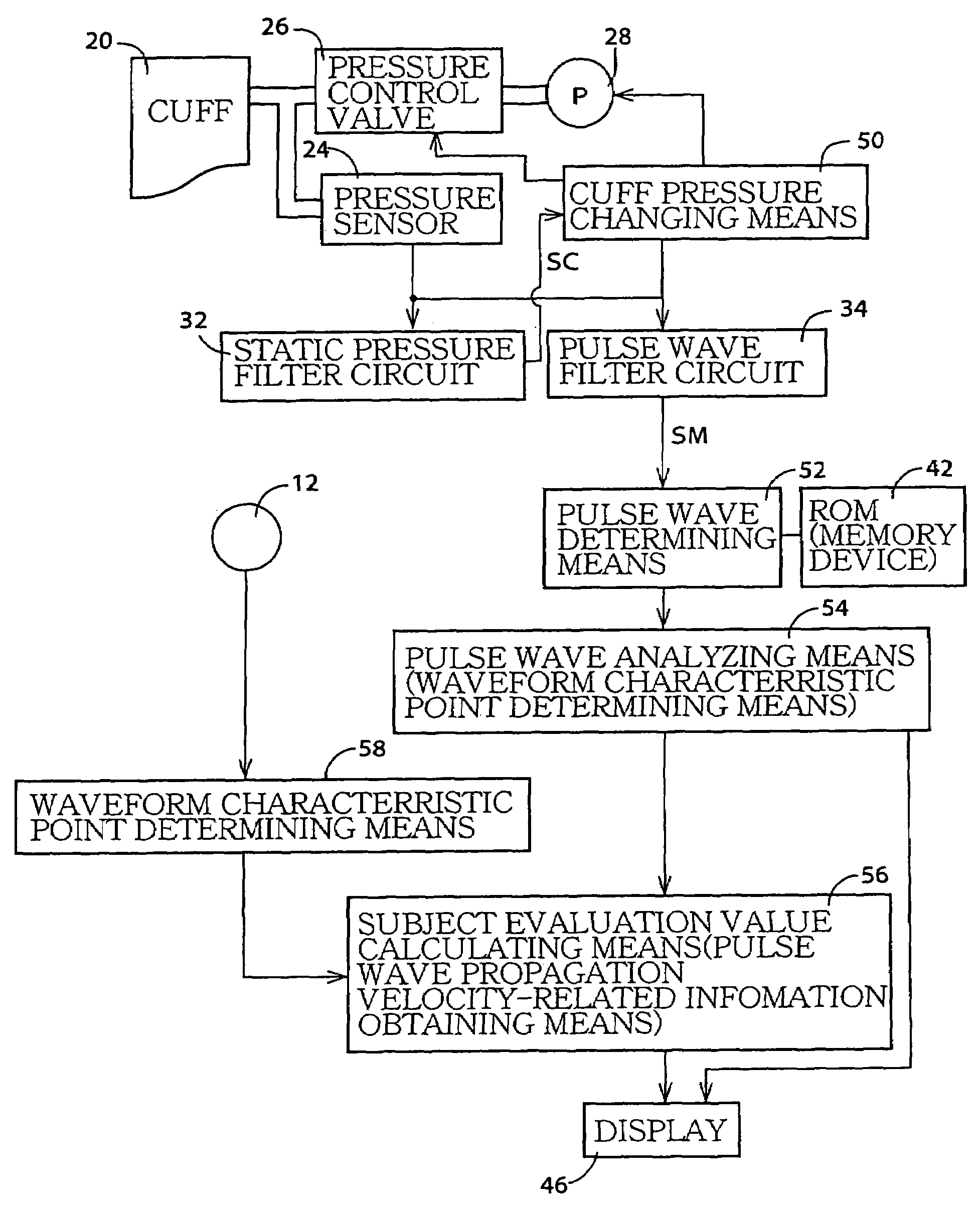
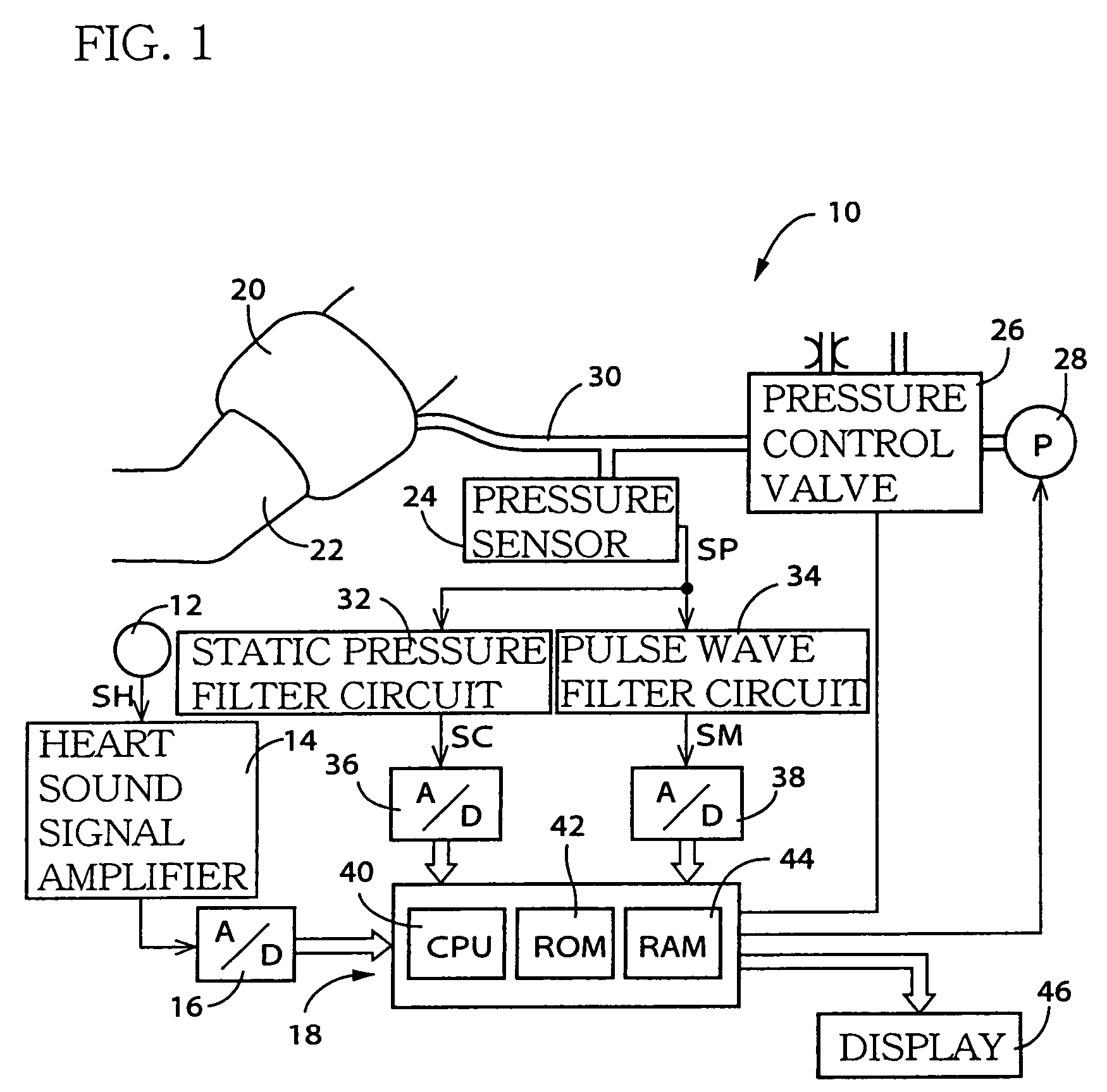
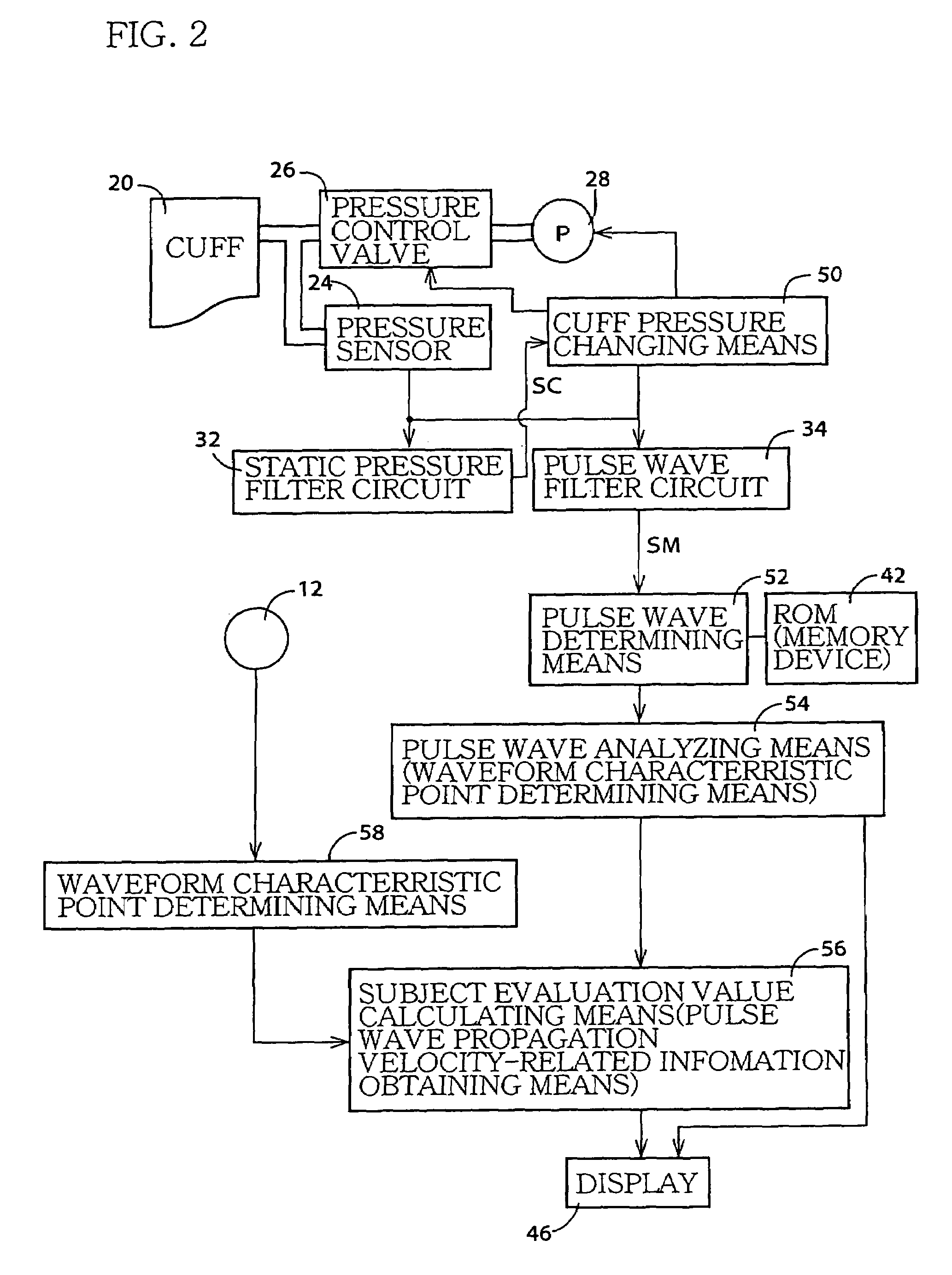
[0032]FIG. 1 is a diagrammatic view for explaining a construction of a subject-evaluation-value obtaining apparatus 10 functioning as a cuff volumetric pulse wave obtaining apparatus, a cuff volumetric pulse wave analyzing apparatus, a pressure pulse wave obtaining apparatus, and a pressure pulse wave analyzing apparatus to each of which the present invention is applied.

[0033]As shown in FIG. 1, the subject evaluation value measuring apparatus 10 includes a heart sound microphone 12 functioning as a second heartbeat synchronous signal detecting device that detects heart sounds as a second heartbeat synchronous signal that is produced in synchronism with a heartbeat of the subject. The heart-sound microphone 12 is attached, with, e.g., an adhesive tape, not shown, to a chest of a living subject, and incorporates a piezoelectric element, not shown, which co...


PUM


Abstract

A subject evaluation value measuring apparatus 10, functioning as a cuff volumetric pulse wave obtaining apparatus, includes a pulse wave determining device (i.e., a cuff volumetric pulse wave determining device) 52 that determines, using an inverse transfer function 1H(f), stored in a ROM (i.e., an inverse transfer function memory) 42, that corresponds to a pre-determined transfer function H(f) between input, i.e., pressure pulsation produced in a cuff 20, and output, i.e., pressure pulsation detected by a pressure sensor 24, a no-delay cuff volumetric pulse wave PK(t) having substantially no delay of transmission, based on an actual cuff pulse wave signal SM outputted by the pressure sensor 24. The thus determined cuff volumetric pulse wave PK(t) is free of waveform distortion and accordingly enjoys high accuracy.

Description

BACKGROUND OF THE INVENTION[0001]1. Field of the Invention[0002]The present invention relates to a pulse wave obtaining apparatus which obtains a cuff volumetric pulse wave produced in a cuff worn on a limb of a living subject, or a pressure pulse wave produced in an artery of a living subject, and a pulse wave analyzing apparatus which analyzes a cuff volumetric pulse wave or a pressure pulse wave.[0003]2. Related Art Statement[0004]A cuff pulse wave as pressure oscillation produced in a cuff (i.e., an inflatable bag) wound around a limb of a living person, in synchronism with heartbeat of the subject, is known as one of a plurality of sorts of information related to person's circulatory organ. Since this pressure oscillation represents the change of volume of blood in person's tissues, including arteries, around which the cuff is wound, it is called a cuff volumetric pulse wave. In addition, a pressure pulse wave as pressure pulsation produced in an artery of a person, in synchron...

Claims


Application Information

Patent Timeline
IPC IPC(8): A61B5/02A61B5/0245A61B5/022A61B5/0275A61B7/04
CPCA61B5/022A61B5/0275A61B7/04A61B5/4035A61B5/4041
Inventor NARIMATSU, KIYOYUKI
Owner FUKUDA DENSHI CO LTD
Why Eureka
Try Eureka