Building decontamination with vaporous hydrogen peroxide

Active Publication Date: 2008-04-22
STERIS CORP
View PDF27 Cites 10 Cited by
  • Summary
  • Abstract
  • Description
  • Claims
  • Application Information

AI Technical Summary

Benefits of technology

[0011]One advantage of the present invention resides in its efficacy in microbially decontaminating ductwork.
[0012]Another advantage of the present invention resides in its efficacy of decontaminating buildings

Problems solved by technology

In older buildings, the ductwork may have an accumulated layer of dust, dirt, and grease.
Large enclosures, such as rooms and buildings tend to become contaminated with a wide variety of microbial contaminants, including bacteria, molds, fungi, yeasts, and the like.
These microorganisms thrive in damp spaces, such as behind walls, in plaster, under counters in bathroooms, and in ductwork and t

Method used


Image

  • Building decontamination with vaporous hydrogen peroxide
  • Building decontamination with vaporous hydrogen peroxide

Examples


Embodiment Construction

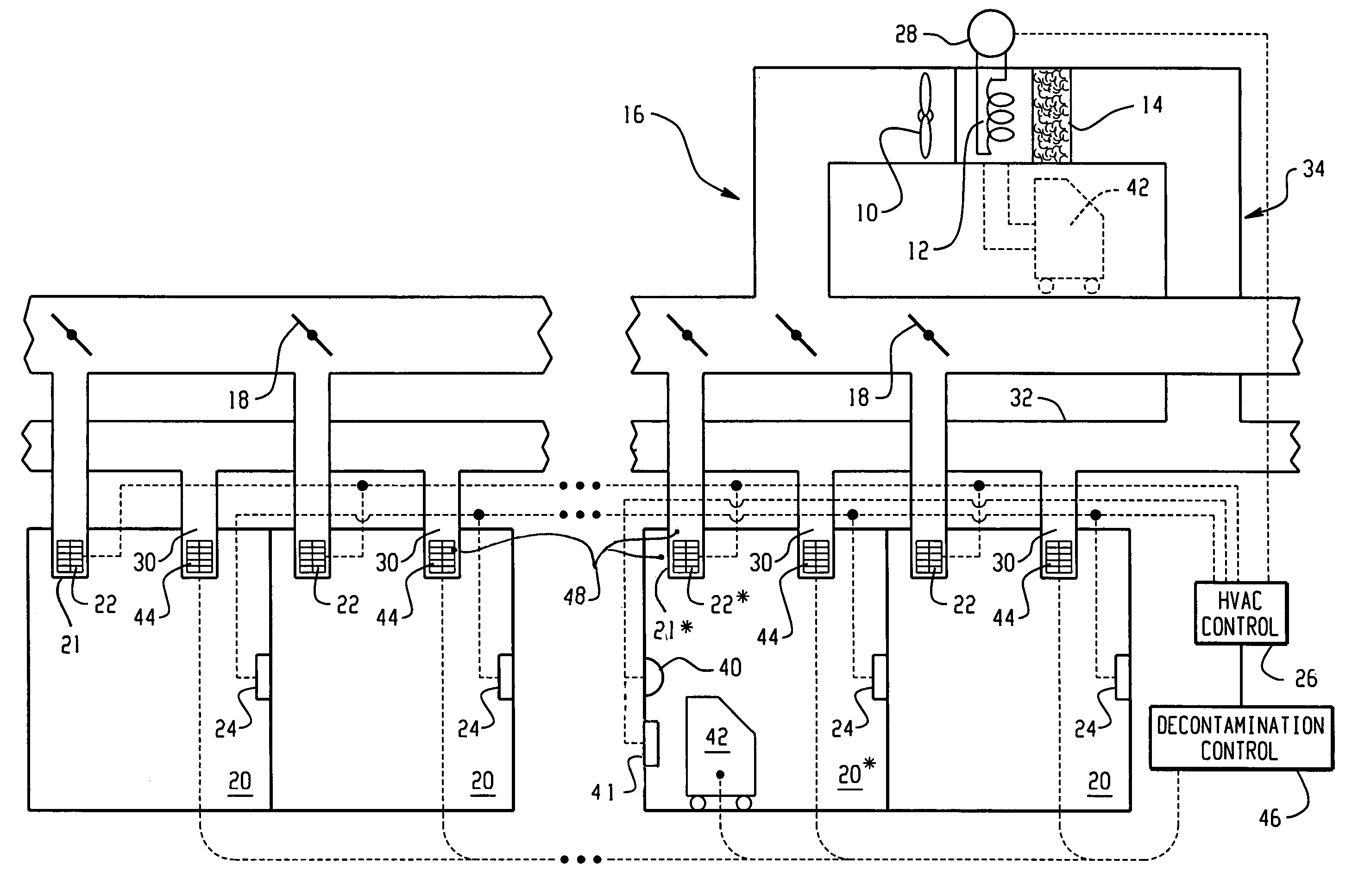
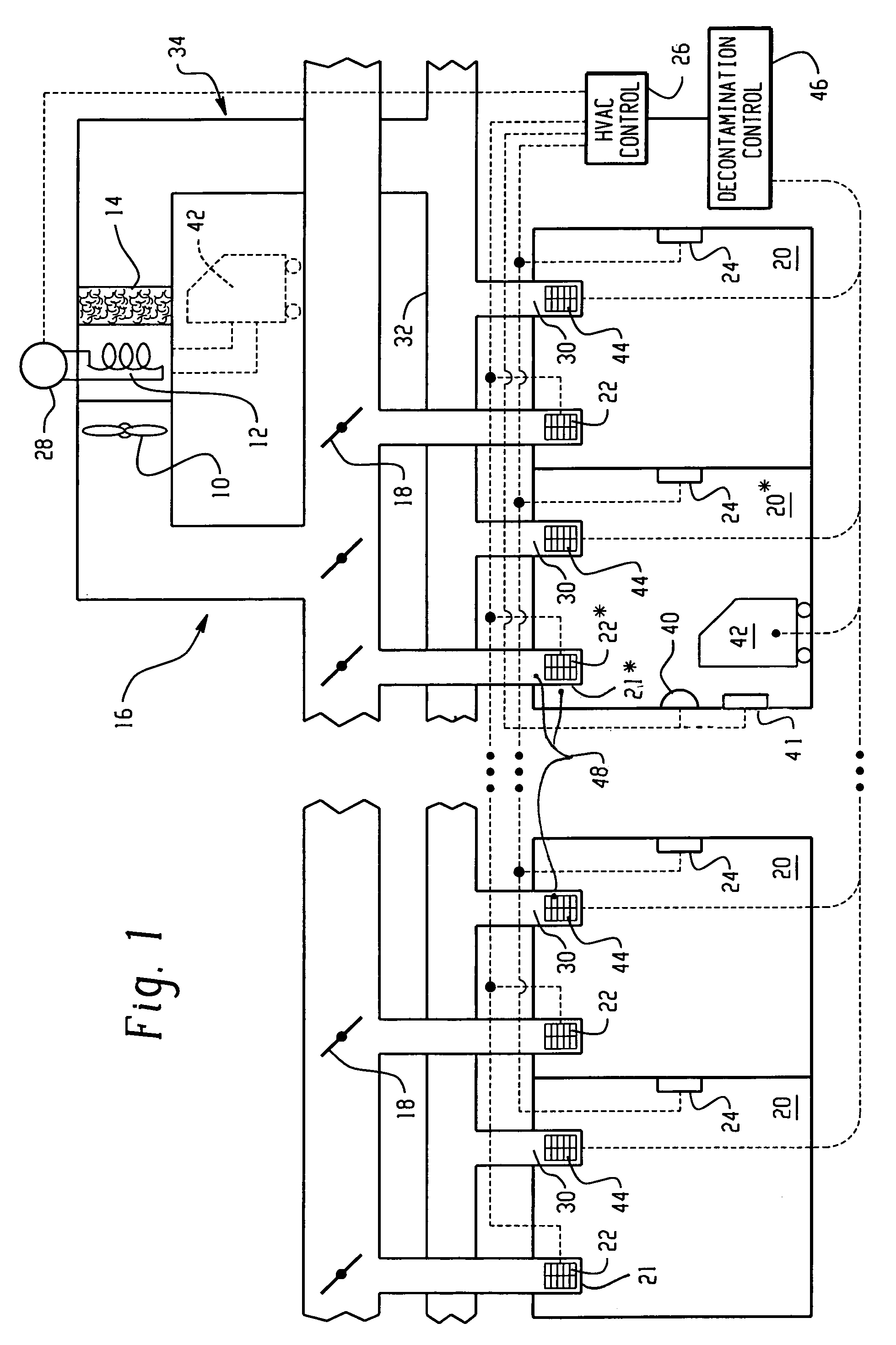
[0016]Commercial buildings and other large enclosures typically include several heat exchanger and delivery and return ductwork subsystems or zones, each heating or cooling a distinct area of the building. In each of a plurality of heating and cooling zones of a large building, a fan or blower 10 draws air through a heat exchanger 12 and a filter 14. The fan propels heated air (in the winter) or cooled air (in the summer) through a delivery duct system 16. The delivery duct system includes branches, turns, and various angles. Adjustable baffles 18 are located at various points within the delivery duct system to control the relative airflow to the various branches.

[0017]The delivery duct system delivers heated or cooled air to each of a plurality of regions, such as offices or other rooms 20. At each room or office, a heat delivery register 21 with a control valve or baffle 22 is connected with the delivery duct system. Preferably, each room or office further includes a thermostat 24...


PUM


Abstract

When microbial contamination is introduced into a room (20*) of an enclosure, such as a building, an HVAC system including supply ductwork (16) and a return ductwork (34) is decontaminated with hydrogen peroxide vapor. A decontamination controller (46) operates controllable baffles (22) at outlet registers (20), temporary controllable baffles (44) at inlet registers (30), and a blower system (10) to circulate hydrogen peroxide vapor from hydrogen peroxide vapor generators (42) through the ductwork in both forward and reverse directions. Further, at least portions of the baffles are closed to create dwell times in which the hydrogen peroxide vapor resides in the ductwork with minimal or turbulent flow.

Description

[0001]This application claims the benefit of U.S. Provisional Application Ser. No. 60 / 444,073, filed on Jan. 31, 2003, which is incorporated herein in its entirety, by reference.BACKGROUND OF THE INVENTION[0002]The present invention relates to the microbial decontamination arts. It finds particular application in conjunction with sporicidal decontamination of heating, ventilation, and cooling (HVAC) systems and will be described with particular reference thereto. However, it is to be appreciated that the present invention is also applicable to other types of microorganisms and to other decontamination applications.[0003]HVAC systems typically include a series of delivery ducts, which deliver heated or cooled air from one or more heat exchangers to individual rooms or offices. The duct is typically largest in cross section adjacent the heat exchanger and diminishes in cross section as it branches to supply treated air to the individual rooms and offices. Typically, baffles at the reg...

Claims


Application Information

Patent Timeline
IPC IPC(8): A61L2/20A61L9/015F24F3/16F24F8/24
CPCA61L2/208A61L2/24A61L9/015F24F3/16A61L2202/14A61L2202/25F24F2003/1664F24F8/20F24F8/24A61L9/046A61L2/26A61L9/12A61L2209/211A61L2209/11
Inventor MCVEY, IAN F.SELIG, VICTOR M.SCHWARTZ, LEWIS I.MCDONNELL, GERALD E.BURKE, PETER A.
Owner STERIS CORP
Why Eureka
Try Eureka