Planar antenna for radio frequency identification tag

a radio frequency identification and planar antenna technology, applied in the direction of antennas, antenna feed intermediates, basic electric elements, etc., can solve the problems of limited identification distance, inability to achieve miniaturization, and inability to have a good conjugate match of innovative planar antennas b>200/b> with tag chips, etc., to achieve good conjugate match and optimize design

Inactive Publication Date: 2008-04-22
TATUNG UNIVERSITY +1
View PDF6 Cites 7 Cited by
  • Summary
  • Abstract
  • Description
  • Claims
  • Application Information

AI Technical Summary

Benefits of technology

[0010]The objective of the present invention is to provide a planar antenna for an RFID tag. Through the optimal design of the height and width of the fractal dipole antenna, the good conjugate match between the planar antenna and the tag chip and the miniaturization of the antenna can be achieved.
[0014]After many times of designs and experiments, the present invention finds when the height of the fractal dipole antenna is 0.3 to 0.7 times of the half wavelength of the electromagnetic signal, and the width of the fractal dipole antenna is 0.7 to 1.1 times of the half wavelength of the electromagnetic signal, the good conjugate match between the planar antenna of the present invention and the tag chip can be achieved.
[0015]On the other hand, after many times of designs and experiments, the present invention finds another optimal size for the fractal dipole antenna. That is, when the height of the fractal dipole antenna is 0.3 to 0.7 times of the half wavelength of the electromagnetic signal, and the width of the fractal dipole antenna is 1 to 2 times of the imaginary part of the impedance value of the tag chip, the good conjugate match between the planar antenna of the present invention and the tag chip can also be achieved. The width mentioned above is in the unit of millimeter, and the imaginary part of the impedance value of the tag chip mentioned above is in the unit of ohm.
[0016]It should be noted that the aforementioned dielectric slab may be a piece of paper and the material of the aforementioned fractal dipole antenna may be conductive printing ink. In other word, the planar antenna of the present invention can be printed by any current printing technique. Therefore, the planar antenna of the present invention has advantages of low cost and mass production.
[0017]To sum up, the present invention limits the length and width of the planar antenna according to the half wavelength of the electromagnetic signals received and transmitted by the planar antenna, or according to the imagery part of the impedance value of the tag chip. By doing this, better conjugate match between the planar antenna and the tag chip and the miniaturization of the antenna can be achieved.

Problems solved by technology

However, as the size of the dipole antenna 120 of the conventional planar antenna 100 is too large, the miniaturization cannot be achieved.
However, though the innovative planar antenna 200 is miniaturized, as the concept of the complex conjugate match is employed, the innovative planar antenna 200 cannot have a good conjugate match with the tag chip.
In other words, when an RFID system is used with the innovative planar antenna which is not of conjugate match, the coverage of the identification distance thereof is limited, thus, they cannot be applied in systems practically.

Method used


Image

  • Planar antenna for radio frequency identification tag
  • Planar antenna for radio frequency identification tag
  • Planar antenna for radio frequency identification tag

Examples


Embodiment Construction

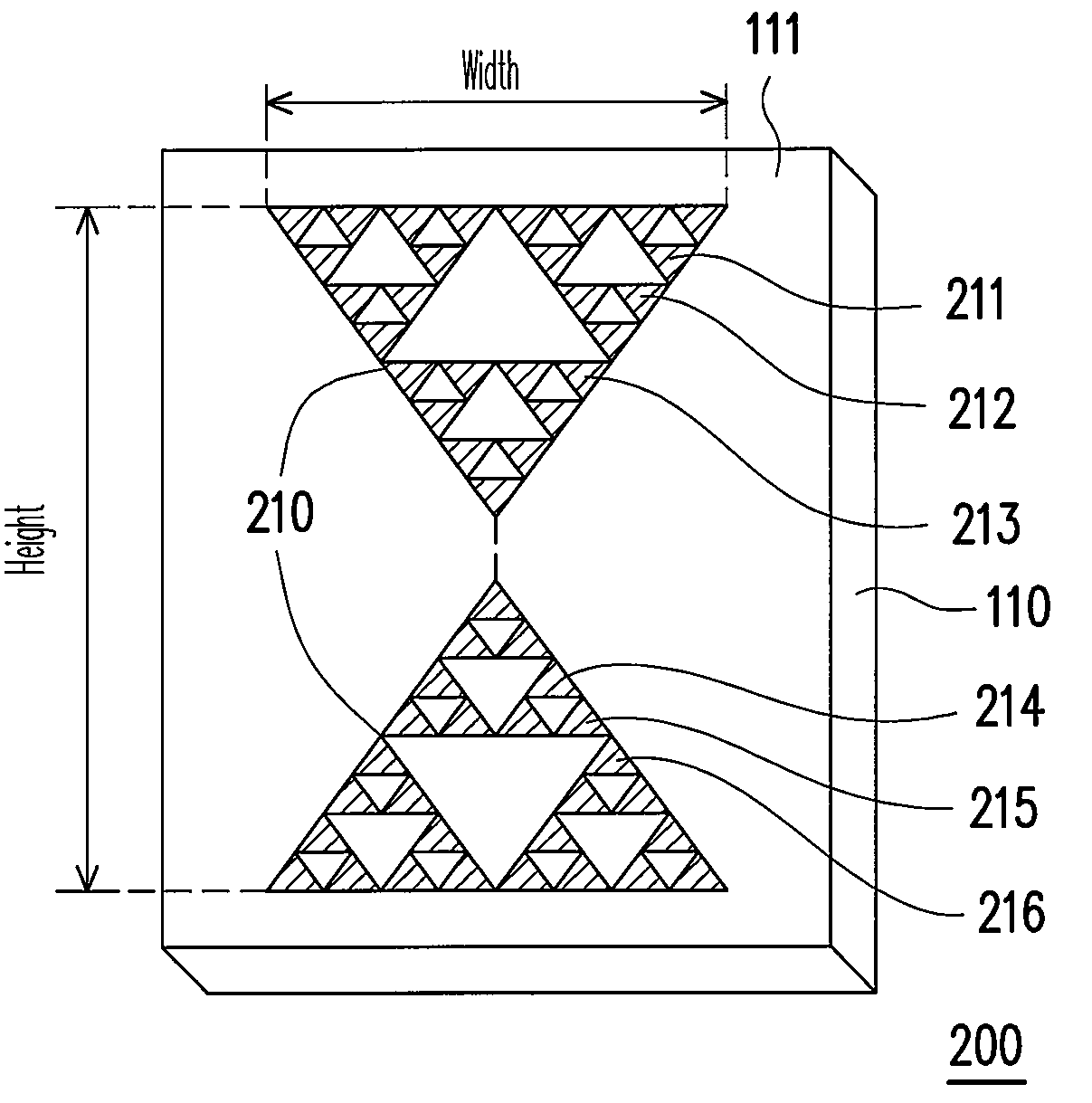
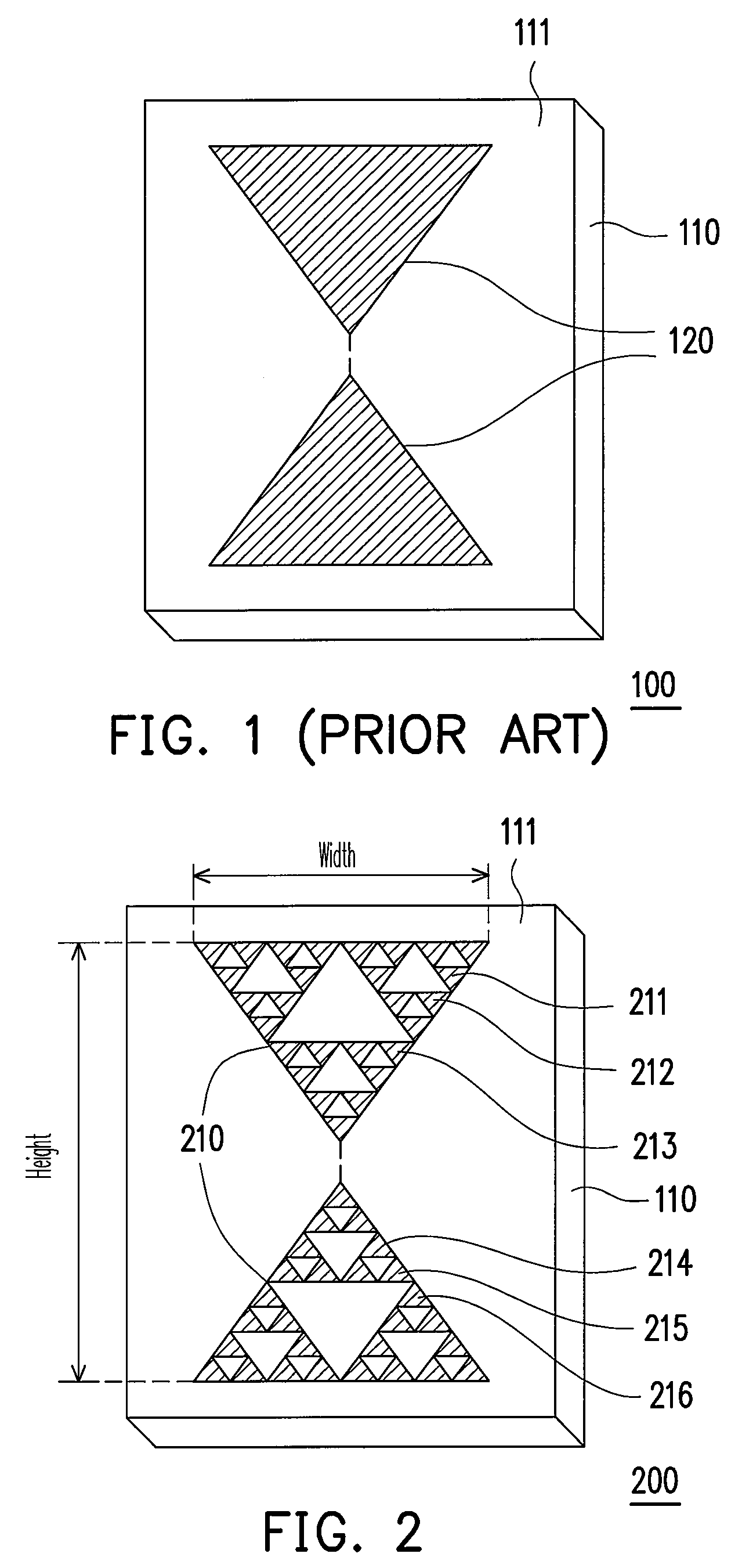
[0023]In order to achieve the miniaturization and conjugate match required by the planar antenna for an RFID tag, the present invention acquires the optimal size of the fractal dipole antenna through many times of designs and experiments. Compared to the innovative planar antennae, the planar antenna of the present invention not only has a miniature appearance, but also effectively improves the identification distance of the RFID system. The planar antenna of the present invention will be described below. However, the description is not intended to limit the present invention. Those skilled in the art can make appropriate modifications to the following embodiments without departing from the spirit of the present invention, and the modifications still fall in the scope of the present invention.

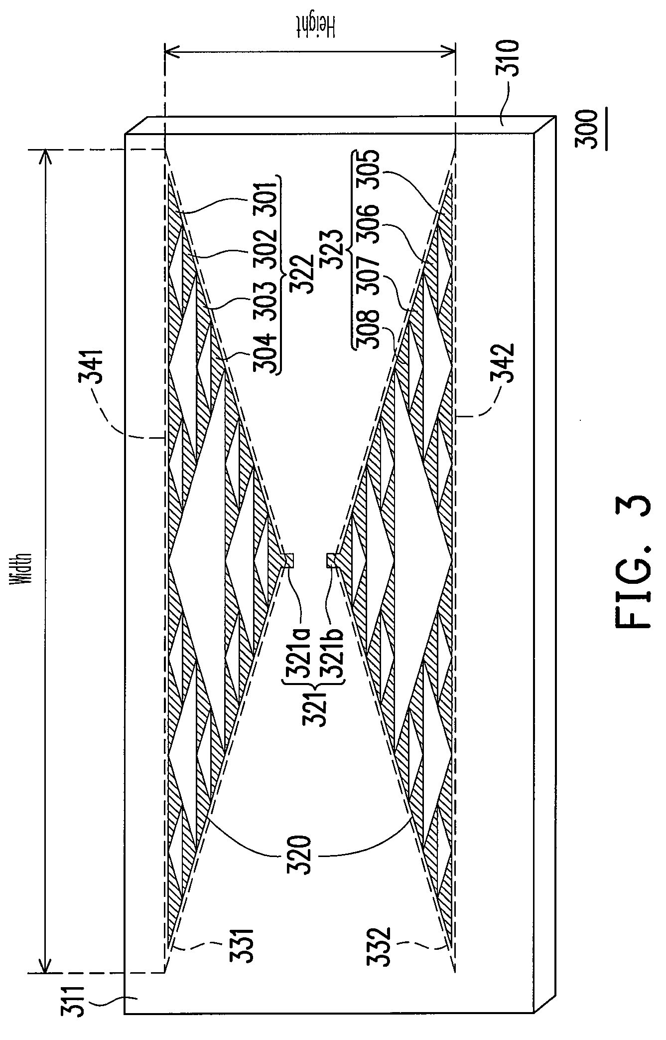
[0024]FIG. 3 is a schematic structural view of a planar antenna for an RFID tag according to an embodiment of the present invention. The planar antenna 300 of the present embodiment comprises a...


PUM


Abstract

A planar antenna for a radio frequency identification tag which receives or transmits an electromagnetic signal is provided. The planar antenna comprises a dielectric slab and a fractal dipole antenna. The height of the fractal dipole antenna is 0.3 to 0.7 times of the half wavelength of the electromagnetic signal, and the width of the fractal dipole antenna is 0.7 to 1.1 times of the half wavelength of the electromagnetic signal. The planar antenna achieves miniaturization and a good matching by utilizing the optimal size of the fractal dipole antenna.

Description

CROSS-REFERENCE TO RELATED APPLICATION[0001]This application claims the priority benefit of Taiwan application serial no. 95123484, filed on Jun. 29, 2006. All disclosure of the Taiwan application is incorporated herein by reference.BACKGROUND OF THE INVENTION[0002]1. Field of Invention[0003]The present invention relates to a planar antenna. More particularly, the present invention relates to a planar antenna for a radio frequency identification (RFID) tag.[0004]2. Description of Related Art[0005]In recent years, RFID systems having the advantages of contactless identification, data security, and being capable of simultaneously reading multiple tags, have gradually replaced the current bar code tag systems. The RFID systems can be applied in very wide fields, such as access control cards, easy cards, and animal identification chips, and can be further applied in fields of logistics management, book management, and medical and drug administration, and so on.[0006]An RFID system mainl...

Claims


Application Information

Patent Timeline
Patent Type & Authority Patents(United States)
IPC IPC(8): H01Q9/28H01Q1/38
CPCH01Q9/285
Inventor HUANG, CHI-FANGZHAN, JING-QING
Owner TATUNG UNIVERSITY
Why Eureka
Try Eureka