Thin-type high-gain UHF RFID (ultrahigh frequency radio frequency identification) anti-metal tag antenna

An anti-metal tag, high-gain technology, which is applied to antennas, antenna supports/mounting devices, and devices that enable antennas to work in different bands at the same time, can solve problems such as antenna failure, difficult processing, and high cost, and achieve good commonality. The effect of yoke matching, good metal resistance and long recognition distance

Active Publication Date: 2017-05-31
HUAQIAO UNIVERSITY
View PDF6 Cites 4 Cited by
  • Summary
  • Abstract
  • Description
  • Claims
  • Application Information

AI Technical Summary

Problems solved by technology

[0003] However, when the tag antenna is placed on a metal surface, due to the impact of the metal surface on the near field of the tag antenna, the input impedance, resonance frequency, pattern and gain of the tag will be rapidly attenuated, resulting in antenna failure
In order to solve the problem of the influence of the metal environment on the working performance of the tag antenna, people have done a lot of research, such as attaching EBG (Electronic Band Gap) dielectric material or artificial magnetic conductor AMC (Artificial Magnetic Conductor) material under the tag antenna, changing the phase of the reflected wave and thus Improve the performance of the tag antenna, but this method is often costly and difficult to process; there are also PIFA tag antennas that use the metal surface as the floor according to the characteristics of the PIFA antenna as a metal floor, but this structure generally requires short-circuit pins or The patch connects the antenna to the floor, which increases the difficulty of processing
[0004] Traditional anti-metal tag antennas will connect the tag antenna to the ground through short-circuit pins, short-circuit vias or short-circuit patches to eliminate the impact of metal surfaces on the performance of the tag antenna, but this will increase the size, production difficulty and cost of the tag antenna. And the size of the metal surface will have a certain impact on the performance of the anti-metal tag antenna

Method used


Image

  • Thin-type high-gain UHF RFID (ultrahigh frequency radio frequency identification) anti-metal tag antenna
  • Thin-type high-gain UHF RFID (ultrahigh frequency radio frequency identification) anti-metal tag antenna
  • Thin-type high-gain UHF RFID (ultrahigh frequency radio frequency identification) anti-metal tag antenna

Examples


Embodiment Construction

[0034] The present invention will be further described below through specific embodiments.

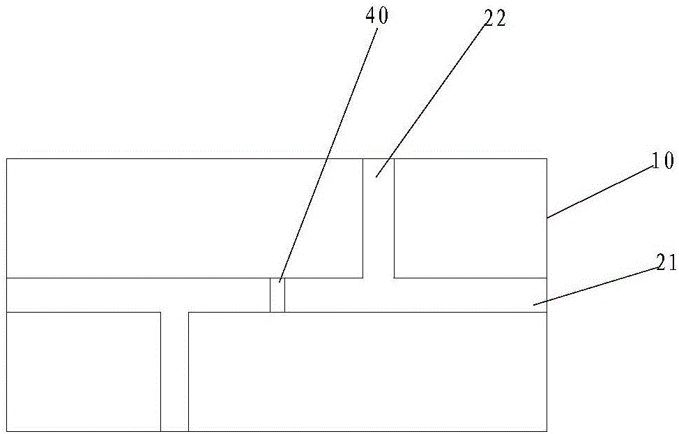
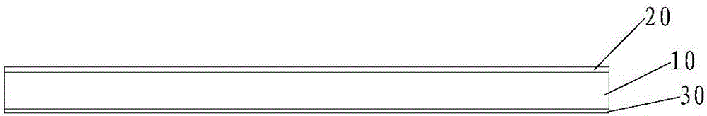
[0035] refer to figure 1 , figure 2 , a thin high-gain UHF RFID anti-metal tag antenna, including a dielectric substrate 10, and an upper metal patch 20 and a lower ground metal patch 30 respectively attached to the upper and lower surfaces of the dielectric substrate 10, the upper metal patch 20 A tag chip 40 is provided. Specifically, the present invention uses alumina ceramics with a dielectric constant εr of 9.8 and a tangent loss angle of tanθ of 0.0015 as the substrate of the antenna, which can effectively maintain the high gain and thickness of the antenna while ensuring that the material is easily available. It can also reduce the impact of the size of the metal surface on the performance of the tag antenna. The length of the dielectric substrate 10 is between 70mm-90mm, the width is between 35mm-45mm, and the thickness is between 0.5mm-1mm. The upper metal patch 20 is pro...


PUM


Abstract

A thin-type high-gain UHF RFID (ultrahigh frequency radio frequency identification) anti-metal tag antenna comprises a dielectric substrate as well as an upper metal patch and a lower grounding metal patch which are attached to the upper and lower surfaces of the dielectric substrate respectively, wherein a tag chip is arranged on the upper metal patch; a first slot and two second slots are formed in the upper metal patch to increase the path of antenna surface current; the first slot transversely penetrates through the upper metal patch; the two second slots longitudinally extend and are connected with two sides of the first slot respectively; the tag chip is connected to the middle of the first slot. According to the antenna, the upper patch of the antenna and the floor are not required to be connected through a short circuit through hole, a short circuit dowel or a short circuit patch. The impedance of the tag antenna can be effectively adjusted by changing the related structures of the first slot and the second slots in the upper metal patch of the antenna, so that good conjugation matching of the tag antenna with the tag chip is realized. The thin-type high-gain UHF RFID anti-metal tag antenna has the advantages of being convenient to process, good in anti-metal property, long in recognition distance and the like.

Description

technical field [0001] The invention relates to the field of tag antennas, in particular to a thin, high-gain UHF RFID anti-metal tag antenna. Background technique [0002] Radio Frequency Identification (RFID) technology is a short-range communication technology that collects and identifies target object information through radio frequency signals. It has been widely valued and developed for its non-contact identification method and high-speed identification efficiency. Among them, Ultra High Frequency (UHF) RFID technology has the advantages of stable performance, long recognition distance, and low cost, so it is widely used in logistics supply, warehouse management, commodity retail and production automation management. . [0003] However, when the tag antenna is placed on a metal surface, due to the impact of the metal surface on the near field of the tag antenna, the input impedance, resonance frequency, pattern and gain of the tag will be rapidly attenuated, resulting...

Claims


Application Information

Patent Timeline
Patent Type & Authority Applications(China)
IPC IPC(8): H01Q1/38H01Q5/10H01Q1/22
CPCH01Q1/22H01Q1/38H01Q5/10
Inventor 袁良昊汤炜孙磊
Owner HUAQIAO UNIVERSITY
Why Eureka
Try Eureka