Backplanes for electro-optic displays

a backplane and electro-optic technology, applied in the field of backplanes for electro-optic displays, can solve the problems of inadequate service life of the backplane, and inability to meet the needs of the user,

a backplane and electro-optic technology, applied in the field of backplanes for electro-optic displays, can solve the problems of inadequate service life of the backplane, and inability to meet the needs of the user,

US7365733B2Inactive Publication Date: 2008-04-29E INK CORPORATION

Image

  • Backplanes for electro-optic displays
  • Backplanes for electro-optic displays
  • Backplanes for electro-optic displays

Examples


Embodiment Construction

[0058]As already indicated, this invention has several different aspects, each providing an improvement in backplanes for electro-optic displays; some aspects of the invention may also be useful in other applications. Hereinafter, the major aspects of the present invention will be described separately, but it should be understood that more than one aspect of the invention may be used in the fabrication of a single backplane or other electronic component. For example, a MEMS backplane of the present invention may be fabricated using an embossing method of the present invention.

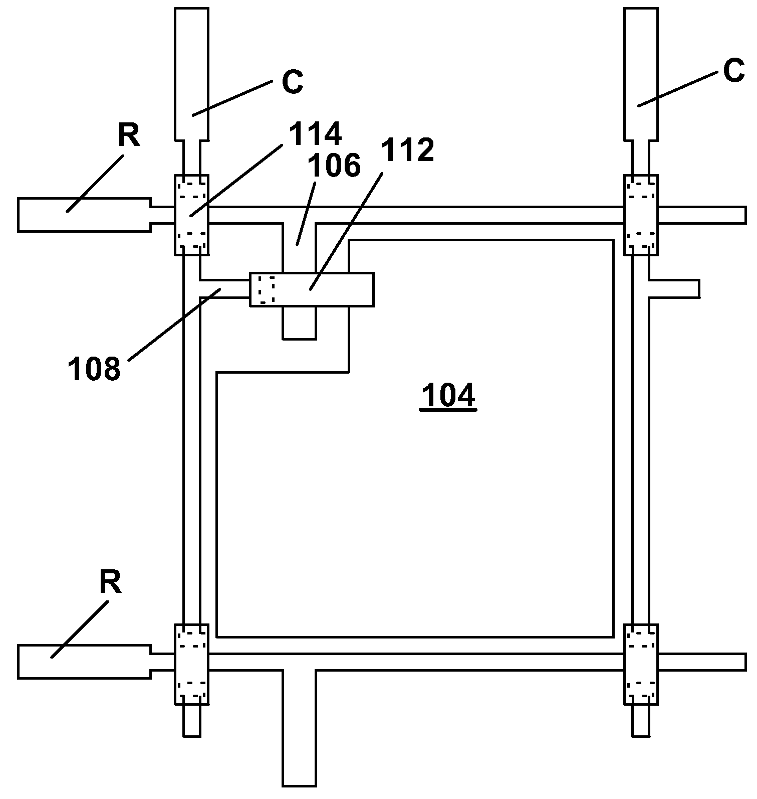
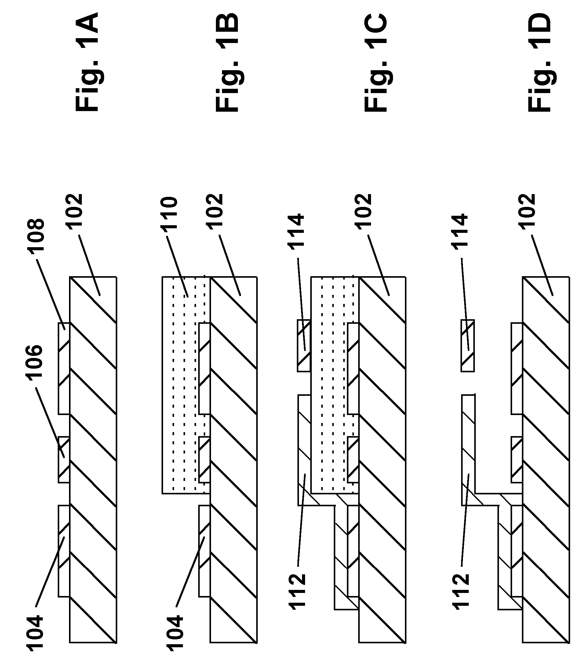
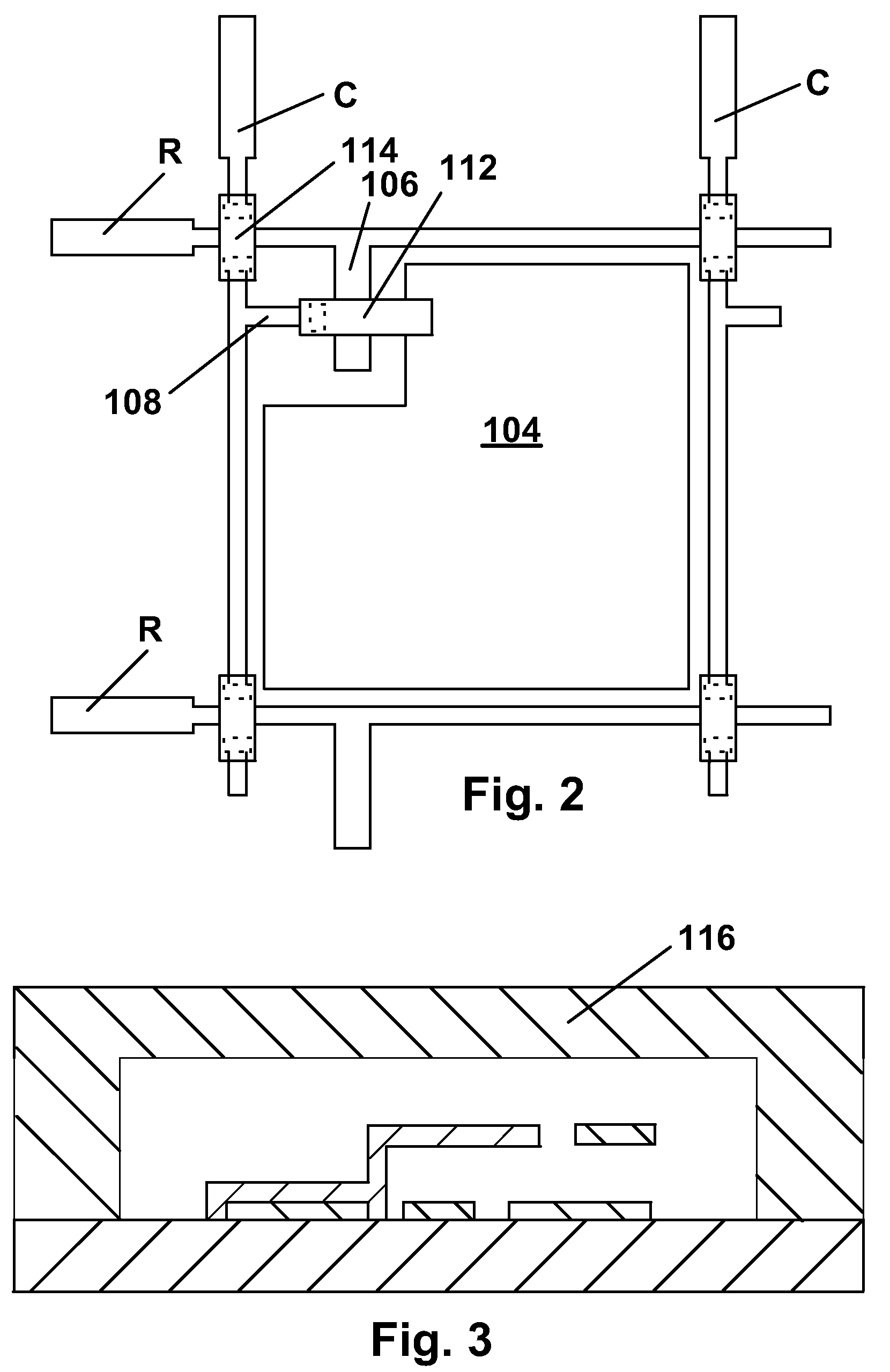
[0059]Part A: MEMS Backplane

[0060]As already discussed, prior art active matrix displays require non-linear (transistor or diode) switching elements at each pixel. Currently non-linear transistor elements may be fabricated from amorphous silicon, polysilicon and organic semiconductors. Diode switching elements include metal insulator metal (MIM), metal semiconductor insulator (MSI), Schottky, and NIN diodes. Th...


PUM

PropertyMeasurementUnit
thicknessaaaaaaaaaa
thicknessaaaaaaaaaa
thicknessaaaaaaaaaa

Abstract

A backplane for an electro-optic display comprises a pixel electrode (104), a voltage supply line (C) arranged to supply a voltage to the pixel electrode (104), and a micromechanical switch (106, 112) disposed between the voltage supply line (C) and the pixel electrode (104), the micromechanical switch (106, 112) having an open state, in which the voltage supply line (C) is not electrically connected to the pixel electrode (104), and a closed state, in which the voltage supply line (C) is electrically connected to the pixel electrode (104).

Description

CROSS REFERENCE TO RELATED APPLICATIONS[0001]This application claims benefit of Application Ser. No. 60 / 319,786, filed Dec. 16, 2002.[0002]This application is also related to copending Application Ser. No. 60 / 375,508, filed Apr. 24, 2002, and application Ser. No. 10 / 249,618, filed Apr. 24, 2003 (now U.S. Pat. No. 7,116,318).BACKGROUND OF INVENTION[0003]This invention relates to backplanes for electro-optic displays, and to processes for the formation of such backplanes. The backplanes of the present invention are especially, but not exclusively, intended for use with particle-based electrophoretic displays in which one or more types of electrically charged particles are suspended in a liquid and are moved through the liquid under the influence of an electric field to change the appearance of the display.[0004]The term “electro-optic” as applied to a material or a display, is used herein in its conventional meaning in the imaging art to refer to a material having first and second dis...

Claims


Application Information

Patent Timeline
29 Apr 2008
Publication
US7365733B2
IPC
G09G3/34; G09G5/00; G02F1/1362; G02F1/167; H01H59/00
CPC
G02F1/1362; G02F1/167; H01H59/0009; G02F1/136213; G02F1/1365; H01H59/00
Inventors
DUTHALER, GREGG M.; ZEHNER, ROBERT W.