
Method and apparatus for performing fast closest match in pattern recognition

a pattern recognition and fast technology, applied in the field of pattern recognition systems, can solve the problems of increasing physical scalability complexity, computationally expensive tasks, and existing hardware solutions with major limitations in scalability, so as to increase the number of processing units and increase the complexity of the system

Active Publication Date: 2008-04-29
META PLATFORMS INC
View PDF84 Cites 56 Cited by
  • Summary
  • Abstract
  • Description
  • Claims
  • Application Information

AI Technical Summary

Benefits of technology

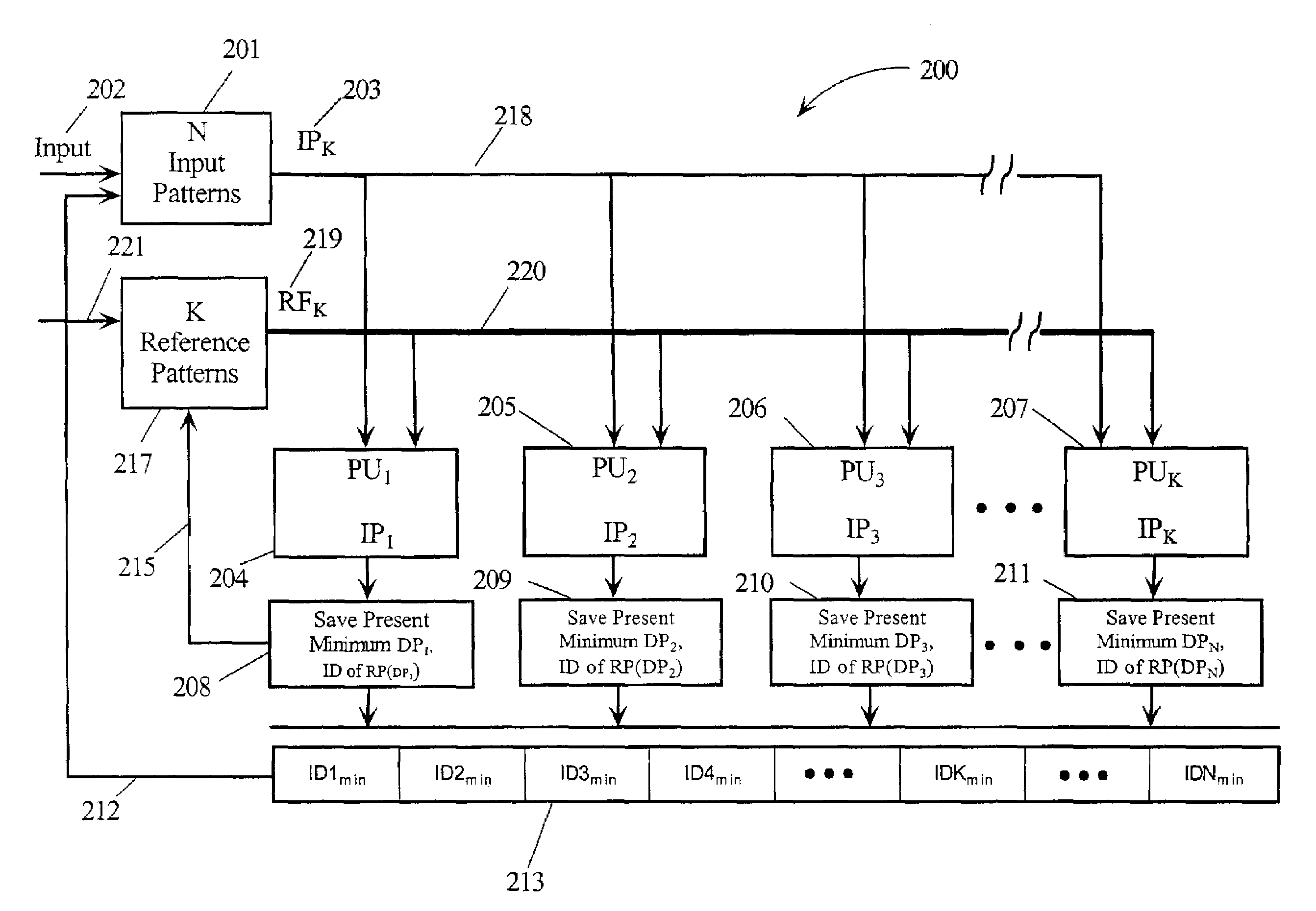
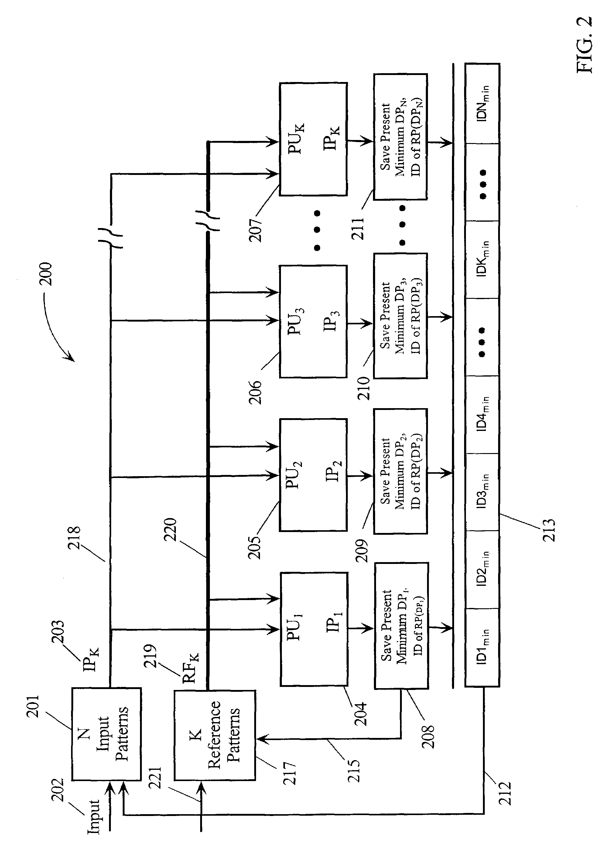
The present invention is a method for finding the closest match of input patterns to reference patterns. It uses a set of processing units that calculate the similarity of each input pattern to the reference pattern and compares the calculated distance to the stored distance. The minimum distance is determined when the last reference pattern is loaded without additional processing. The invention allows for scaling by increasing the number of processing units without adding additional circuitry outside of the processing units. The technical effect of the invention is to provide a fast and efficient way to find the closest match of input patterns to reference patterns.

Problems solved by technology

Closest match determination is used in many applications like image processing or in image classification and is a very computationally expensive task.
Hardware is needed for real-time applications but existing hardware solutions have some major limitations concerning scalability.
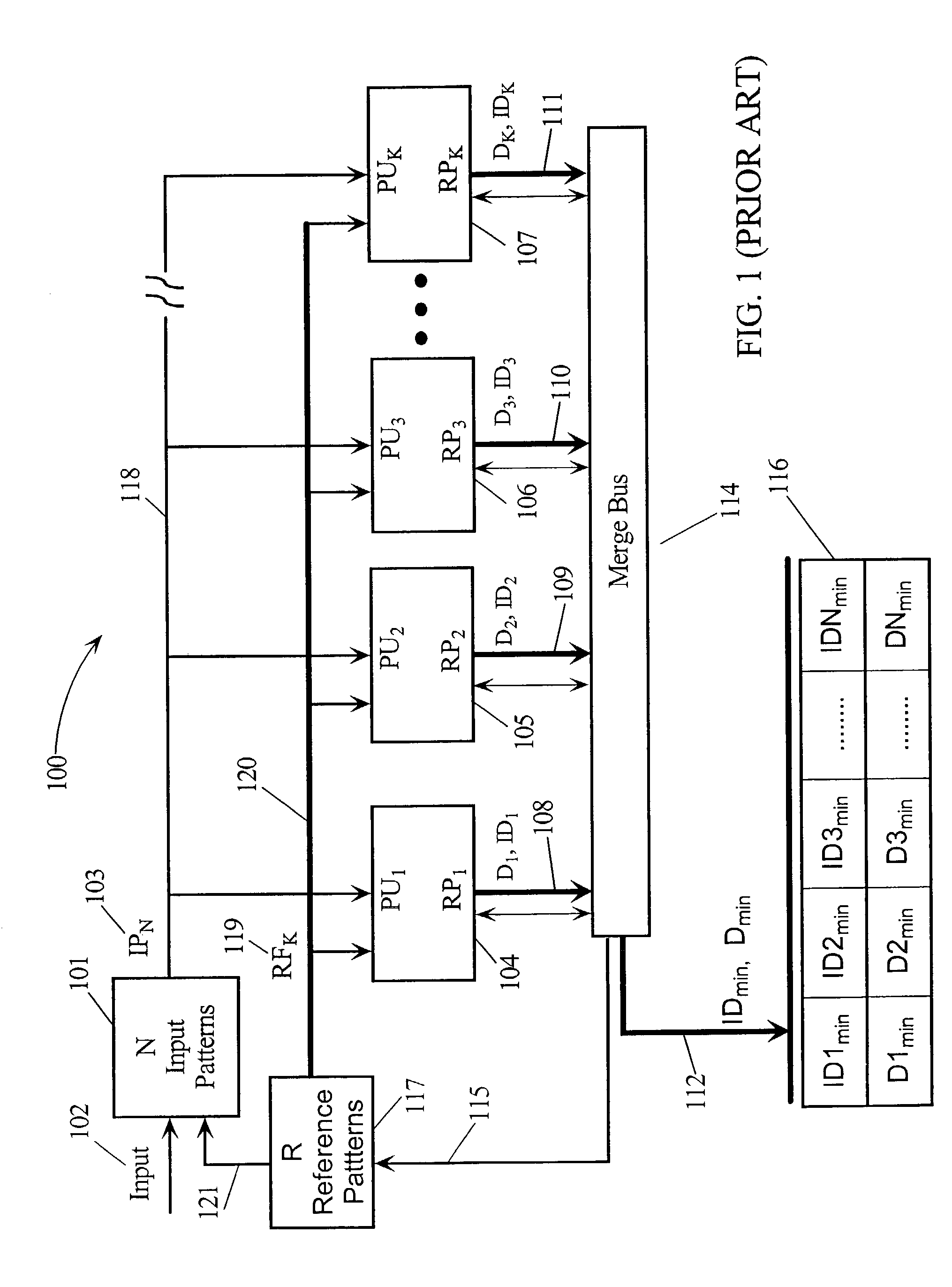
There are several problems with this prior art method.
The common bus also makes the physical scalability more complex.
Because one also needs common circuitry to merge together all PUs, the process is relatively slow.
Therefore, the prior art implementation of finding the minimum value is typically slower than desired.
Another problem occurs if the number of RPs is greater than the number of available PUs.
This must be repeated for each set of patterns and is relatively slow, causing major scalability problems with respect to the number RPs.

Method used


Image

  • Method and apparatus for performing fast closest match in pattern recognition
  • Method and apparatus for performing fast closest match in pattern recognition
  • Method and apparatus for performing fast closest match in pattern recognition

Examples


Embodiment Construction

[0035]In the following description, numerous specific details are set forth to provide a thorough understanding of the present invention. However, it will be obvious to those skilled in the art that the present invention may be practiced without such specific details. In other instances, well-known circuits may be shown in block diagram form in order not to obscure the present invention in unnecessary detail. For the most part, details concerning timing considerations and the like have been omitted in as much as such details are not necessary to obtain a complete understanding of the present invention and are within the skills of persons of ordinary skill in the relevant art.

[0036]Refer now to the drawings wherein depicted elements are not necessarily shown to scale and wherein like or similar elements are designated by the same reference numeral through the several views. Specific variables may be shown in italic to distinguish them from other variables.

[0037]FIG. 5 is a block diag...


PUM


Abstract

A method and apparatus for determining a closest match of N input patterns relative to R reference patterns using K processing units. Each of a set of input patterns are loaded into the K processing units. One of the Reference patterns is sequentially loaded into each of the processing units and a distance defining the similarity between the reference pattern and each of the input patterns is calculated. A present calculated distance replaces its corresponding stored present minimum distance if it is has a smaller value. After the R reference patterns have been processed the minimum distance and its corresponding identification for all N input patterns is determined without merging outputs. The minimum distances and the identifications may be read either in parallel or serially. The apparatus is easily scalable by adding processors. The number of reference patterns may be easily increased without altering system configuration.

Description

CROSS REFERENCE TO RELATED APPLICATIONS[0001]This application is related to the following commonly owned copending U.S. patent applications:[0002]Ser. No. 10 / 393,296 entitled “Method and Apparatus For Imbedded Pattern Recognition Using Dual Alternating Pointers” filed Mar. 20, 2003, and[0003]Ser. No. 10 / 393,139 entitled “Method and Apparatus For Finding Repeated Substrings In Pattern Recognition” filed Mar. 20, 2003, which are hereby incorporated by reference herein.TECHNICAL FIELD[0004]The present invention relates in general to pattern recognition systems and in particular to pattern recognition systems where a closest match between an input pattern is determined relative to a set of reference patterns.BACKGROUND INFORMATION[0005]Recognizing patterns within a set of data is important in many fields, including speech recognition, image processing, seismic data, etc. Some image processors collect image data and then pre-process the data to prepare it to be correlated to reference da...

Claims


Application Information

Patent Timeline
Patent Type & Authority Patents(United States)
IPC IPC(8): G06K9/62G06K9/00
CPCG06K9/00973G06V10/94
Inventor KRAVEC, KERRY A.SAIDI, ALI G.SLYFIELD, JAN M.TANNHOF, PASCAL R.
Owner META PLATFORMS INC
Learn More