Adjustment of ventilator pressure-time profile to balance comfort and effectiveness

a ventilator and time profile technology, applied in the field of mechanical ventilation, can solve the problems of not automaticly adjusting the waveform, unsuitable non-invasive (mask) ventilation, and disadvantage of proportional assist ventilators for patients with abnormal chemoreflexes

Inactive Publication Date: 2008-05-06
RESMED LTD
View PDF35 Cites 132 Cited by
  • Summary
  • Abstract
  • Description
  • Claims
  • Application Information

AI Technical Summary

Benefits of technology

[0013]One broad concept implemented by the invention is to change the pressure waveform in a way that makes an advantageous trade-off between comfort and efficiency, using a more efficient but less comfortable waveform only when needed.
[0015]In particular, the servo-controller increases the degree of support by increasing the pressure modulation amplitude, and also by generating a progressively more square, and therefore efficient, pressure waveform; the servo-controller decreases the degree of support by decreasing the pressure modulation amplitude, and by generating a progressively more smooth and therefore comfortable pressure waveform. The changes in amplitude and squareness can be performed sequentially, or partially or completely simultaneously.

Problems solved by technology

Also, the system is intolerant of leak, so is unsuitable for non-invasive (mask) ventilation.
In such prior art, the clinician selects a particular waveform, but thereafter the waveform does not change, and there is no automatic adjustment of the waveform.
However, a proportional assist ventilator is disadvantageous for a patient with abnormal chemoreflexes, as inadequate support is provided during pathological reductions in effort such as central apneas and hypopneas.
A disadvantage of the pressure waveform template shown in FIG. 1 is that it is less efficient than a square wave.
This can be a problem in patients who require a very high degree of support, or in the case of mouth leak, where in order to provide a desired pressure modulation amplitude at the glottic inlet, a much higher pressure modulation amplitude must be supplied at the mask.
The use of pure resistive unloading is similarly inefficient for the same reason: the area under the pressure-vs-time curve is only half that of a square wave of the same amplitude.
Even the combination of the smooth waveform template with resistive unloading is less efficient than a square wave of the same amplitude.

Method used


Image

  • Adjustment of ventilator pressure-time profile to balance comfort and effectiveness
  • Adjustment of ventilator pressure-time profile to balance comfort and effectiveness
  • Adjustment of ventilator pressure-time profile to balance comfort and effectiveness

Examples


Embodiment Construction

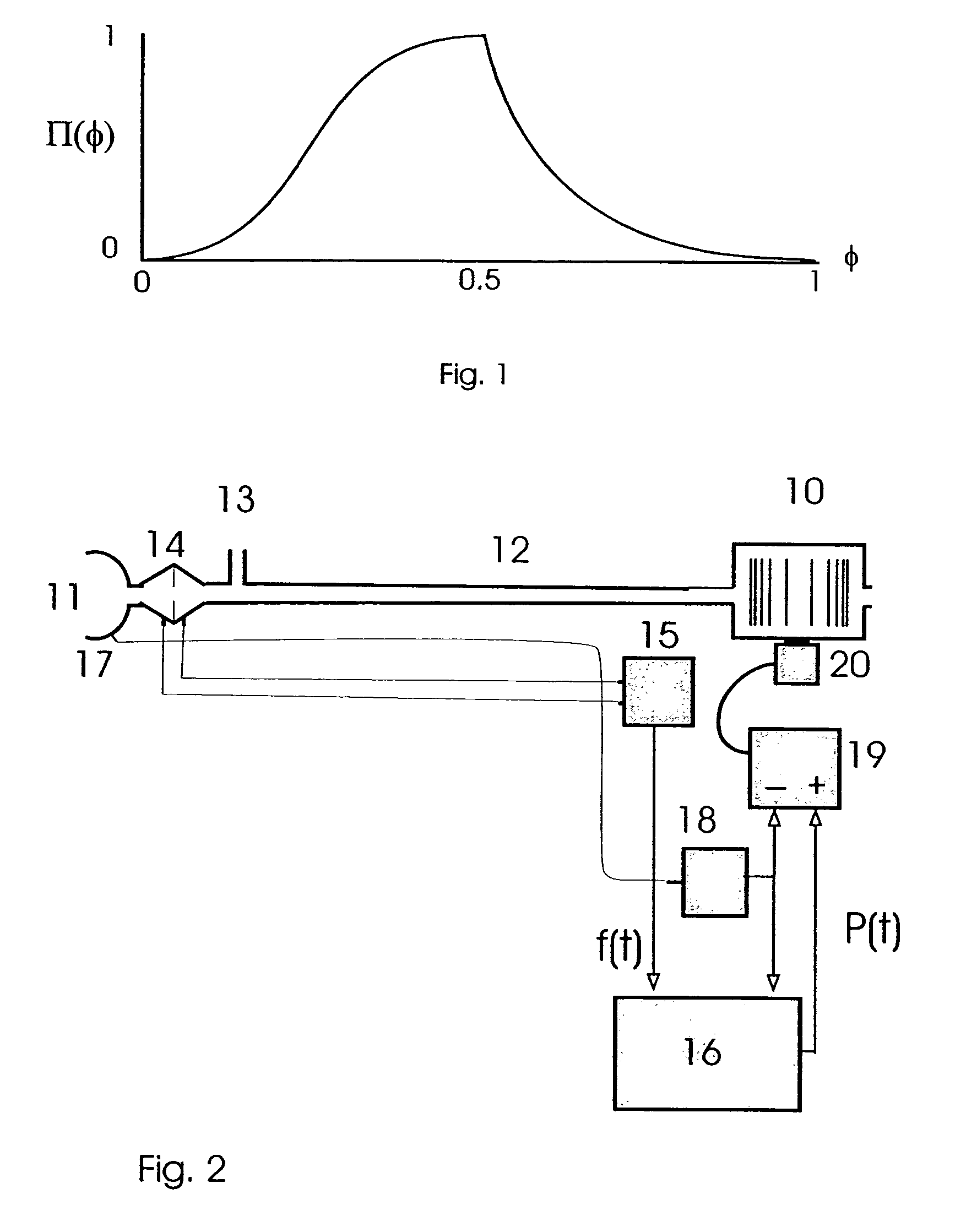
[0020]Suitable apparatus for implementing the invention is shown in FIG. 2. The apparatus provides breathable gas at controllable positive pressure to a patient's airway. In the drawing, a blower 10 supplies breathable gas to a mask 11 in communication with a patient's airway via a delivery tube 12 and exhausted via an exhaust 13. Airflow at the mask 11 is measured using a pneumotachograph 14 and a differential pressure transducer 15. The mask flow signal f(t) from the transducer 15 is then sampled by a microprocessor 16. Mask pressure is measured at the port 17 using a pressure transducer 18. The pressure signal from the transducer 18 is then sampled by the microprocessor 16. The microprocessor sends an instantaneous mask pressure request (i.e., desired mask pressure) signal P(t) to a servo-controller 19, which compares the pressure request signal with the actual pressure signal from the transducer 18 to control a fan motor 20. Microprocessor settings can be adjusted via a serial p...


PUM


Abstract

The invention is a ventilator whose servo-controller adjusts the degree of support by adjusting the profile of the pressure waveform as well as the pressure modulation amplitude. As the servo-controller increases the degree of support by increasing the pressure modulation amplitude, it also generates a progressively more square, and therefore efficient, pressure waveform; when the servo-controller decreases the degree of support by decreasing the pressure modulation amplitude, it also generates a progressively more smooth and therefore comfortable pressure waveform.

Description

[0001]This application is a continuation of U.S. patent application Ser. No. 10 / 424,344, filed on Apr. 28, 2003 now U.S. Pat. No. 6,755,193, which is a continuation of U.S. patent application Ser. No. 09 / 518,101, filed on Mar. 3, 2000, now U.S. Pat. No. 6,553,992.FIELD OF THE INVENTION[0002]This invention relates to the field of mechanical ventilation, and more particularly to machines and methods for providing a patient with ventilatory support.BACKGROUND[0003]Conventional ventilators provide ventilatory support by utilizing a number of different pressure-time profiles. In its simplest form, a ventilator delivers airflow at a fixed rate (or some other fixed function of time such as sinusoidally), and the airway pressure increases passively as a function of the mechanical properties of the patient's respiratory system. Such a ventilator is in general suitable only for a paralyzed and sedated patient who cannot change his / her ventilation at will. Also, the system is intolerant of lea...

Claims


Application Information

Patent Timeline
Patent Type & Authority Patents(United States)
IPC IPC(8): A61M16/00A61B5/08A61B5/087
CPCA61M16/00A61M16/0069A61M2016/0036A61M2205/15A61M2205/3344A61M16/0858A61M16/024
Inventor BERTHON-JONES, MICHAELBATEMAN, PETERMALOUF, GORDON
Owner RESMED LTD
Why Eureka
Try Eureka