Pendulation control system with active rider block tagline system for shipboard cranes

a control system and active rider technology, applied in the field of cranes, can solve the problems that the control system and method known in the art for facilitating crane operation are not entirely successful in limiting or alleviating pendulation to acceptable magnitudes under all standard operating conditions

Active Publication Date: 2008-05-06
THE UNITED STATES OF AMERICA AS REPRESENTED BY THE SECRETARY OF THE NAVY
View PDF29 Cites 112 Cited by
  • Summary
  • Abstract
  • Description
  • Claims
  • Application Information

AI Technical Summary

Benefits of technology

[0014]Pendulation control analogous to that characterizing PCS is uniquely brought to bear by the present invention with respect to a stewing pedestal crane of the type that incorporates a rider block tagline system (RBTS). The present invention uniquely features active control of the rider block. The addition of this active control element permits the inverse kinematics (ship motion cancellation) commands to be optimally partitioned between the crane's primary and RBTS drive systems. Furthermore, the active swing damping commands can be fully implemented through the active rider block, thus entirely eliminating active swing damping as a requirement imposed on the primary crane drive system.

Problems solved by technology

Due to its greater complexity as compared with a simple slewing pedestal crane, an RBTS-equipped slewing pedestal crane demands greater dexterity and decision-making from the crane operator.
Pendulation—swinging or swaying of the payload attached to one or more hoist lines—is a fundamental problem associated with control of a slewing pedestal crane.
Generally speaking, control systems and methods known in the art for facilitating crane operation are not entirely successful in limiting or alleviating pendulation to acceptable magnitudes under all standard operating conditions.

Method used


Image

  • Pendulation control system with active rider block tagline system for shipboard cranes
  • Pendulation control system with active rider block tagline system for shipboard cranes
  • Pendulation control system with active rider block tagline system for shipboard cranes

Examples


Embodiment Construction

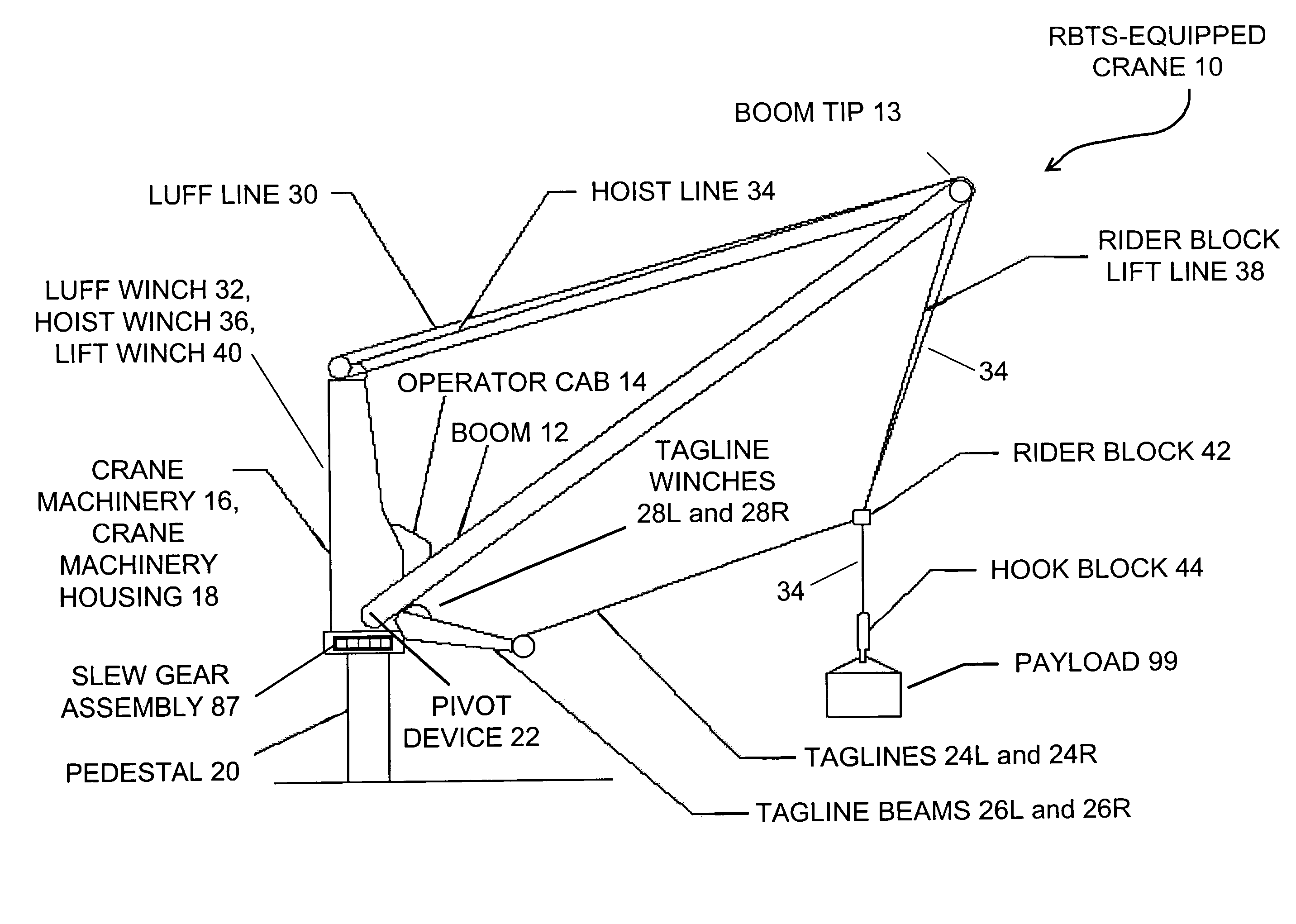
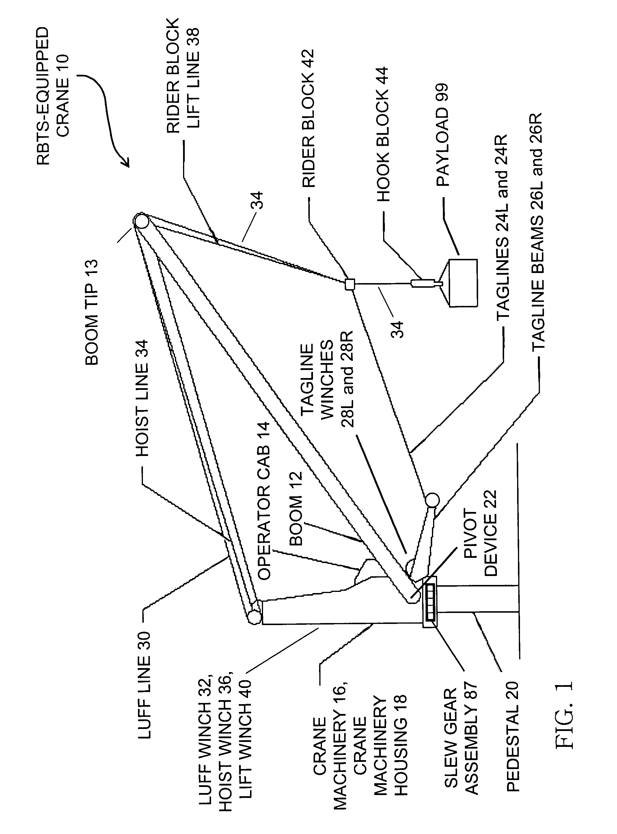
[0031]Reference is now made to FIG. 1, which shows an RBTS-equipped crane without the present invention's methodology applied thereto. Conventional RBTS-equipped crane 10 includes boom 12 (which includes a boom tip 13), operator cab 14, crane machinery 16, crane machinery housing 18, slew gear assembly 87, pedestal (base) 20, pivot device 22, taglines 24L and 24R, outriggers (tagline beams) 26L and 26R, tagline winches 28L and 28R, luff line 30, luff winch 32, payload hoist line 34, hoist winch 36, rider block lift line 38, lift winch 40, rider block 42, and hook block 44. Payload (load) 99 is suspended from hook block 44. The ordinarily skilled artisan understands that parts and components not indicated in FIG. 1 may also be included in RBTS-equipped crane 10. It is also understood that each of luff line 30, hoist line 34, and lift line 38, though nominally singularized herein, may actually include plural discrete linear structures such as wires or cables.

[0032]RBTS-equipped crane ...


PUM


Abstract

The inventive control system, as typically embodied, includes sensing mechanisms, a computational processing unit, and an algorithm for processing inputs and generating outputs to control a rotating pedestal crane equipped with a Rider Block Tagline System (RBTS). Typical inventive embodiments uniquely feature a processing algorithm that distributes various control modes that operate not only through the crane's hoisting, luffing, and slewing mechanisms but also through the crane's RBTS; the inventive algorithm thereby effectuates motion compensation and pendulation damping with respect to the crane. This algorithmic allocation of control represents a more efficient crane anti-pendulation methodology than conventional methodologies; in particular, the inventive methodology exerts significantly greater control of the payload while exacting significantly less burden upon the hoisting, luffing, and slewing mechanisms of the crane.

Description

STATEMENT OF GOVERNMENT INTEREST[0001]The invention described herein may be manufactured and used by or for the Government of the United States of America for governmental purposes without payment of any royalties thereon or therefor.BACKGROUND OF THE INVENTION[0002]The present invention relates to cranes, more particularly to methodologies for controlling pendulation that is associated with motion of suspended payloads during operation of cranes, such as rotary boom (slewing pedestal) cranes mounted aboard ships for transferring cargo to piers or other ships.[0003]Crane technology is prevalent in a variety of settings for effecting lift-on, lift-off transfer of cargo. A “gantry crane” implements a horizontally moveable trolley from which a payload is suspended. A “slewing pedestal crane” (also commonly referred to as a “rotary boom crane” or a “rotary jib crane”) involves the suspension of a payload from the tip of a rotatable “boom” (“jib”). According to a “simple” type of slewing...

Claims


Application Information

Patent Timeline
Patent Type & Authority Patents(United States)
IPC IPC(8): B66C23/53
CPCB66C13/063Y10S254/90
Inventor AGOSTINI, MICHAEL J.BIRD, III, J. DEXTERGREEN, JEFFREY P.LEBAN, FRANK A.PARKER, GORDON G.
Owner THE UNITED STATES OF AMERICA AS REPRESENTED BY THE SECRETARY OF THE NAVY
Why Eureka
Try Eureka