

Optical film, and glass
a technology of optical film and glass, applied in the field of optical film, can solve the problems of insufficient light shielding degree from oblique directions, increased production cost, and need for improvement, so as to reduce light intrusion into indoor rooms, improve brightness contrast in rooms, and prevent increases in room temperature
- Summary
- Abstract
- Description
- Claims
- Application Information
AI Technical Summary
Benefits of technology
Problems solved by technology
Method used
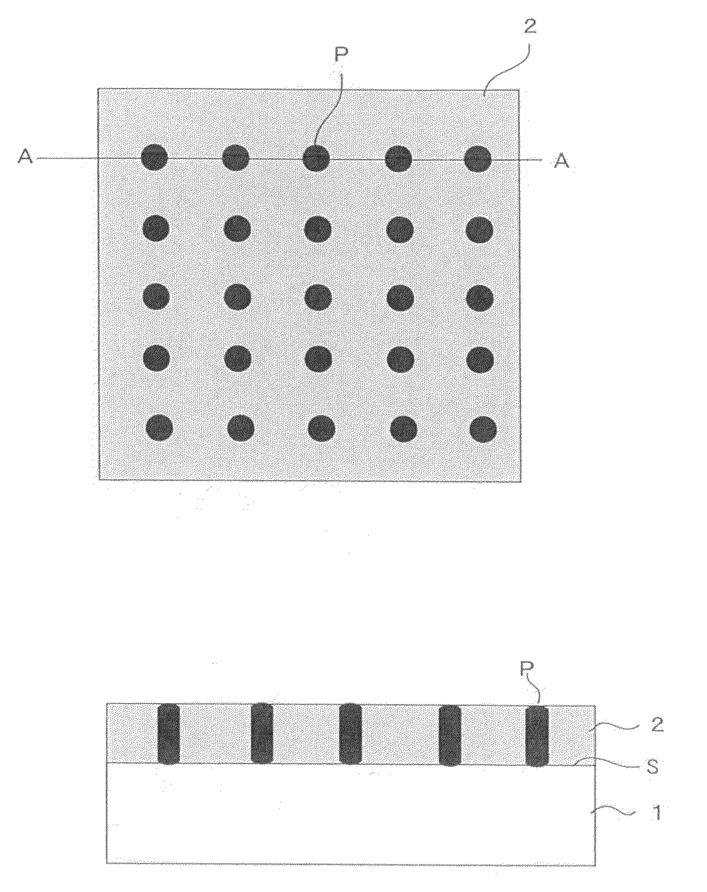
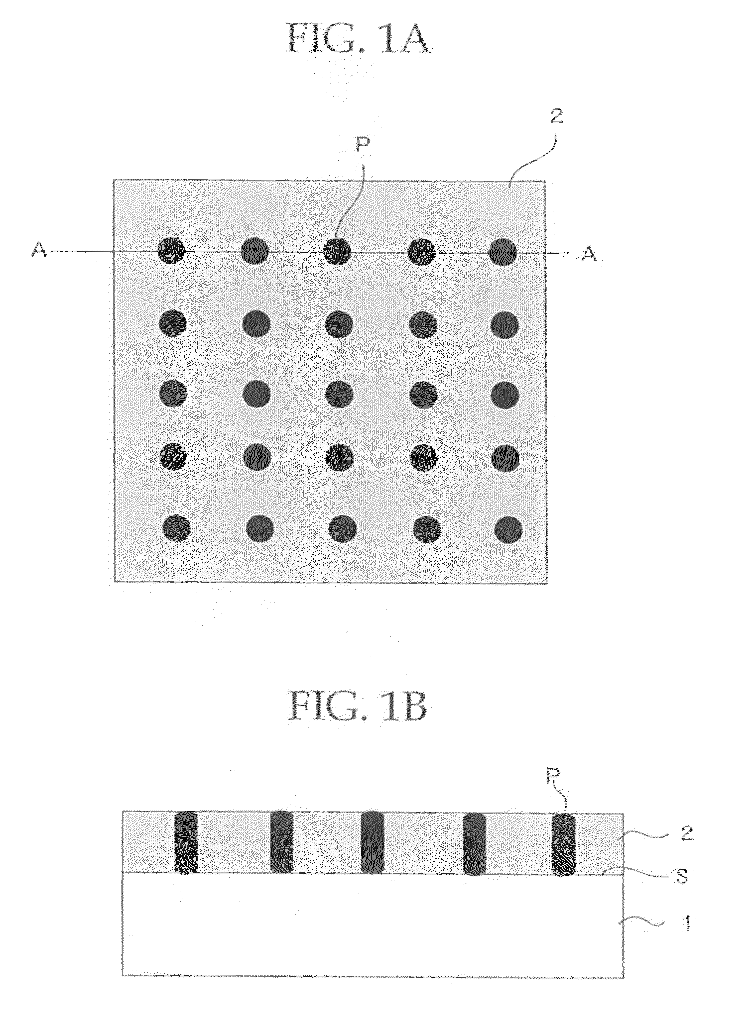
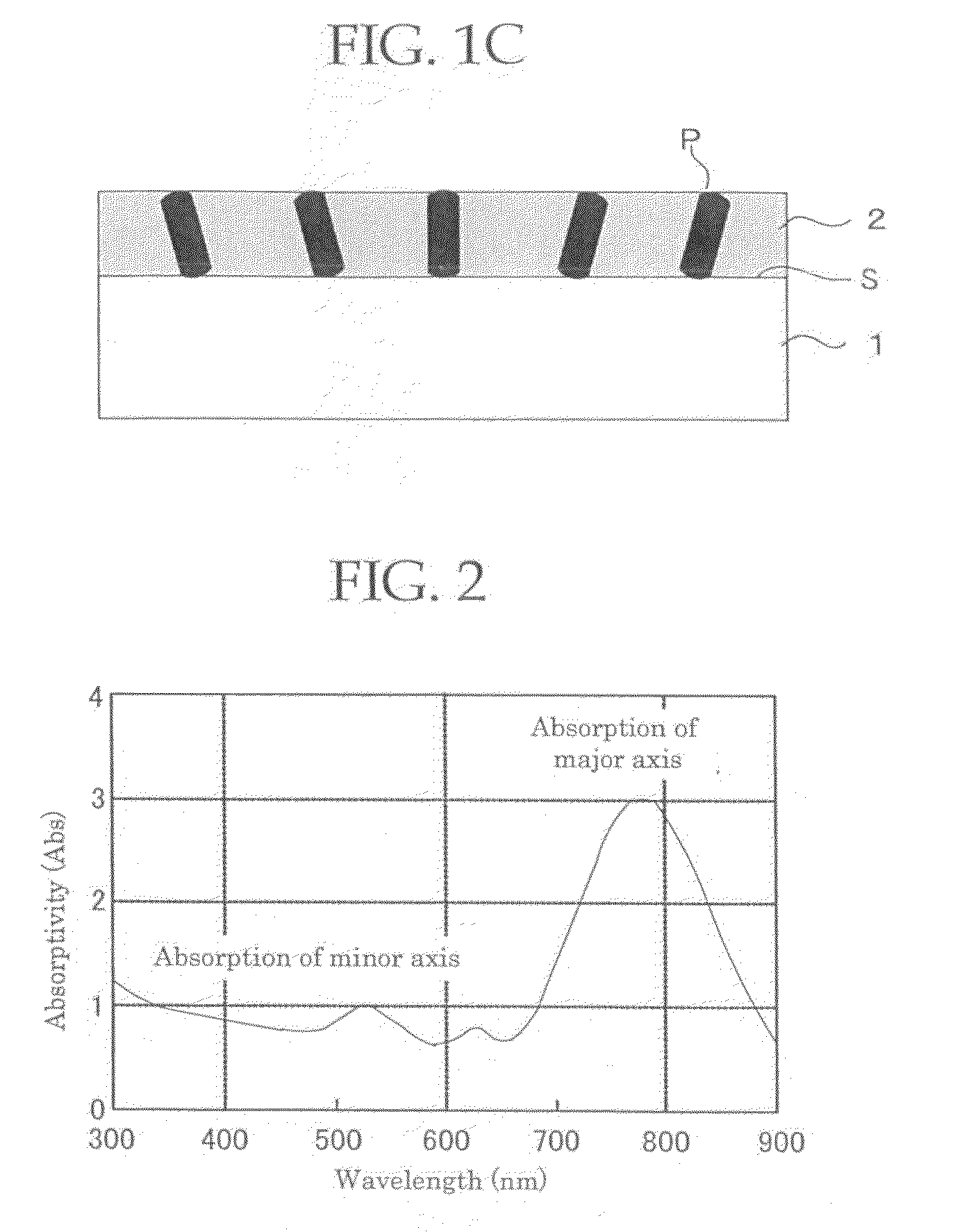
Image

Examples
example 1
Preparation of Half-Wavelength Plate
[0242]A polycarbonate film (brand name: PURE ACE, manufactured by Teijin Chemicals, Ltd.) was heated and drawn to set the birefringence value (retardation value at a wavelength of 550 nm) at 275 nm and to thereby prepare a half-wavelength plate.
—Formation of Polarized Film—
[0243]The both surfaces of the half-wavelength plate was spin-coated with a oriented film solution of polyvinyl alcohol (PVA) (methanol solution) at 1,000 rpm for 30 seconds and then dried at 100° C. for 3 minutes to thereby prepare a perpendicularly oriented film of PVA having a thickness of 1.0 μm.
—Preparation of Polarized Film Coating Solution—
[0244]To a liquid crystal solution in which 3.04 g of a liquid crystal compound (brand name: PALIOCOLOR LC242, manufactured by BASF Corporation) having a photo-polymerizable group was dissolved in 5.07 g of methylethylketone (MEK), 1.11 g of an initiator solution [0.90 g of IRGACURE 907 (manufactured by Chiba Specialty Chemicals K.K.) a...
example 2
Preparation of Film Formed with Polarizer in which a Gold Nano-Rod is Oriented, By Anodic Oxidation Alumina Method
[0251]—Formation of Half-Wavelength Plate Formed with Transparent Conductive Film—
[0252]A polycarbonate film (brand name: PURE ACE, manufactured by Teijin Chemicals, Ltd.) was heated and drawn to set the birefringence value (retardation value at a wavelength of 550 nm) at 275 nm and to thereby prepare a half-wavelength plate. On the both surfaces of the half-wavelength plate, an ITO (Tin-doped Indium oxide) film was formed so as to form a film thickness of 120 nm to thereby prepare a half-wavelength plate formed with a transparent conductive film of 10 Ω / square in resistivity.
—Formation of Aluminum-Deposited Film—
[0253]On a surface of the transparent conductive film of the half-wavelength plate formed with the transparent conductive film, an aluminum-deposited film having a film thickness of 150 nm was formed by RF sputtering method.
[0254]—Formation of Nanoholes by Anodi...
example 3
Preparation of Laminated Glass
[0260]The optical film of Example 1 was sandwiched in between two sheets of transparent PVB films, further both surfaces of the PVB films were covered with a float glass, the laminate was put in a rubber bag, the rubber gag was deaerated at a vacuum degree of 2,660 Pa for 20 minutes and placed in an oven in a state of being deaerated and further subjected to a vacuum press while maintaining the temperature of 90° C. for 30 minutes. The laminated glass that was preliminarily bonded as above was pressure-bonded in an auto-clave for 20 minutes under the conditions of 135° C. and a pressure of 118N / cm2 to thereby prepare a laminated glass.
[0261]The partition effect and light resistance of the obtained laminated glass were evaluated in the same manner as in Example 1. Table 1 shows the evaluation results.
PUM
| Property | Measurement | Unit |
|---|---|---|
| aspect ratio | aaaaa | aaaaa |
| aspect ratio | aaaaa | aaaaa |
| aspect ratio | aaaaa | aaaaa |
Abstract
Description
Claims
Application Information