
Conformal tricuspid annuloplasty ring and template

a tricuspid annuloplasty and template technology, applied in the field of medical devices, can solve the problems of severe debilitating valve disease, excessive backward flow of blood through the valve, and even death of valves

Inactive Publication Date: 2008-05-06
EDWARDS LIFESCIENCES CORP
View PDF31 Cites 32 Cited by
  • Summary
  • Abstract
  • Description
  • Claims
  • Application Information

AI Technical Summary

Benefits of technology

The present invention provides an annuloplasty ring that is designed to reinforce the tricuspid annulus, which is a heart valve. The ring has a flexible structure that allows it to bend at the two free ends, with the posterior side being shorter and having a smaller radius of curvature than the anterior side. The ring body includes an inner structural support of multiple bands of elastic material, which are embedded in a matrix of pliable material. The ring body may also have a cross-section that changes around its length. The invention also provides an annuloplasty ring template for surgical use, which has a rigid body with a peripheral mounting ring that follows a three-dimensional path. The mounting ring has a plurality of cutting guides for inserting the annuloplasty ring and a shallower slot for receiving a suture to secure the ring. The technical effects of the invention include improved heart valve function and reduced risk of complications during heart valve replacement surgery.

Problems solved by technology

Diseased heart valves may be categorized as either stenotic, wherein the valve does not open sufficiently to allow adequate forward flow of blood through the valve, and / or incompetent, wherein the valve does not close completely, causing excessive backward flow of blood through the valve when the valve is closed.
Valve disease can be severely debilitating and even fatal if left untreated.

Method used


Image

  • Conformal tricuspid annuloplasty ring and template
  • Conformal tricuspid annuloplasty ring and template
  • Conformal tricuspid annuloplasty ring and template

Examples


Embodiment Construction

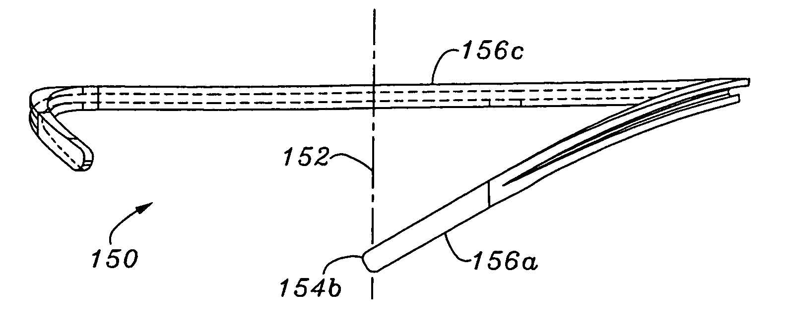
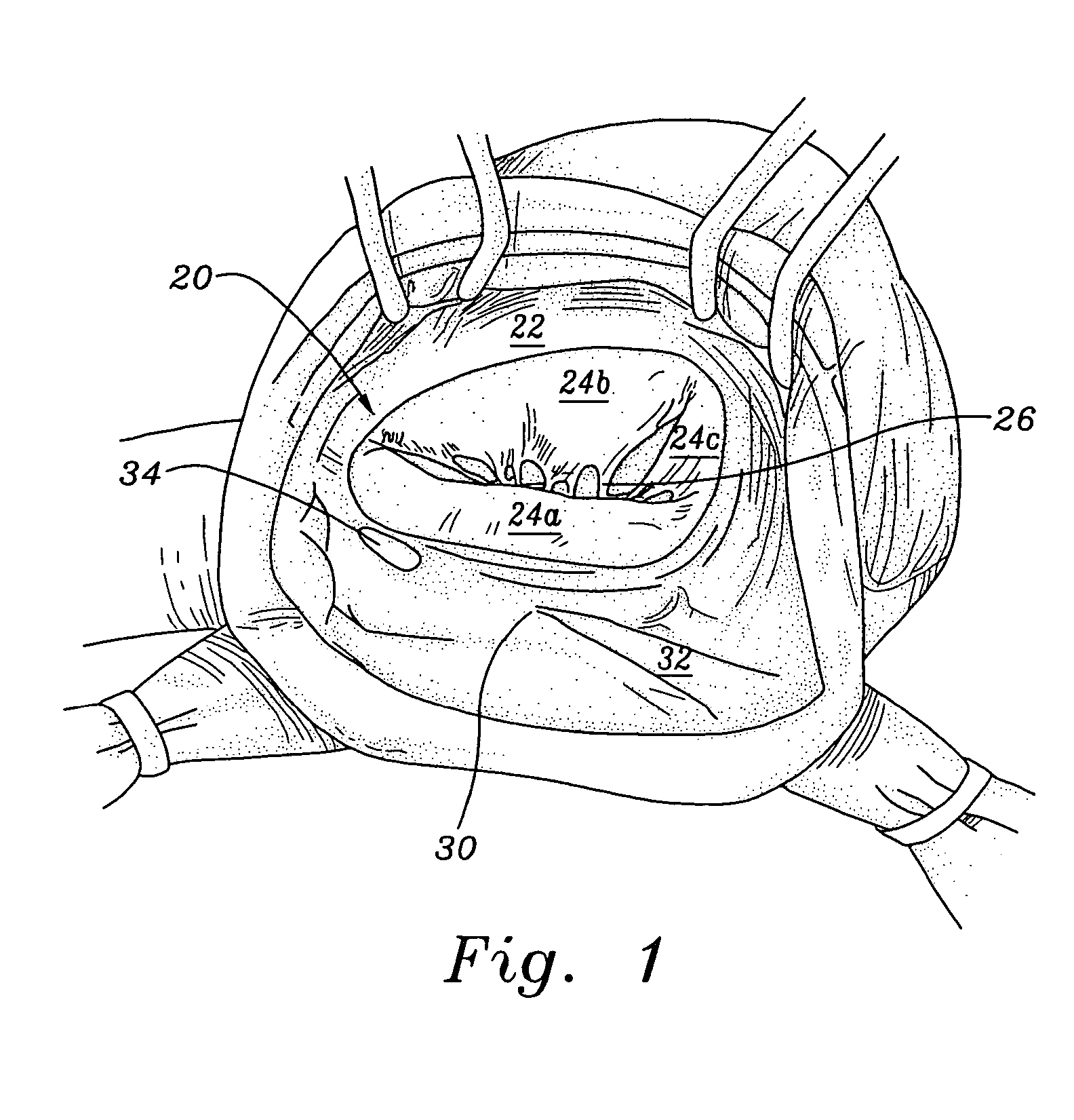
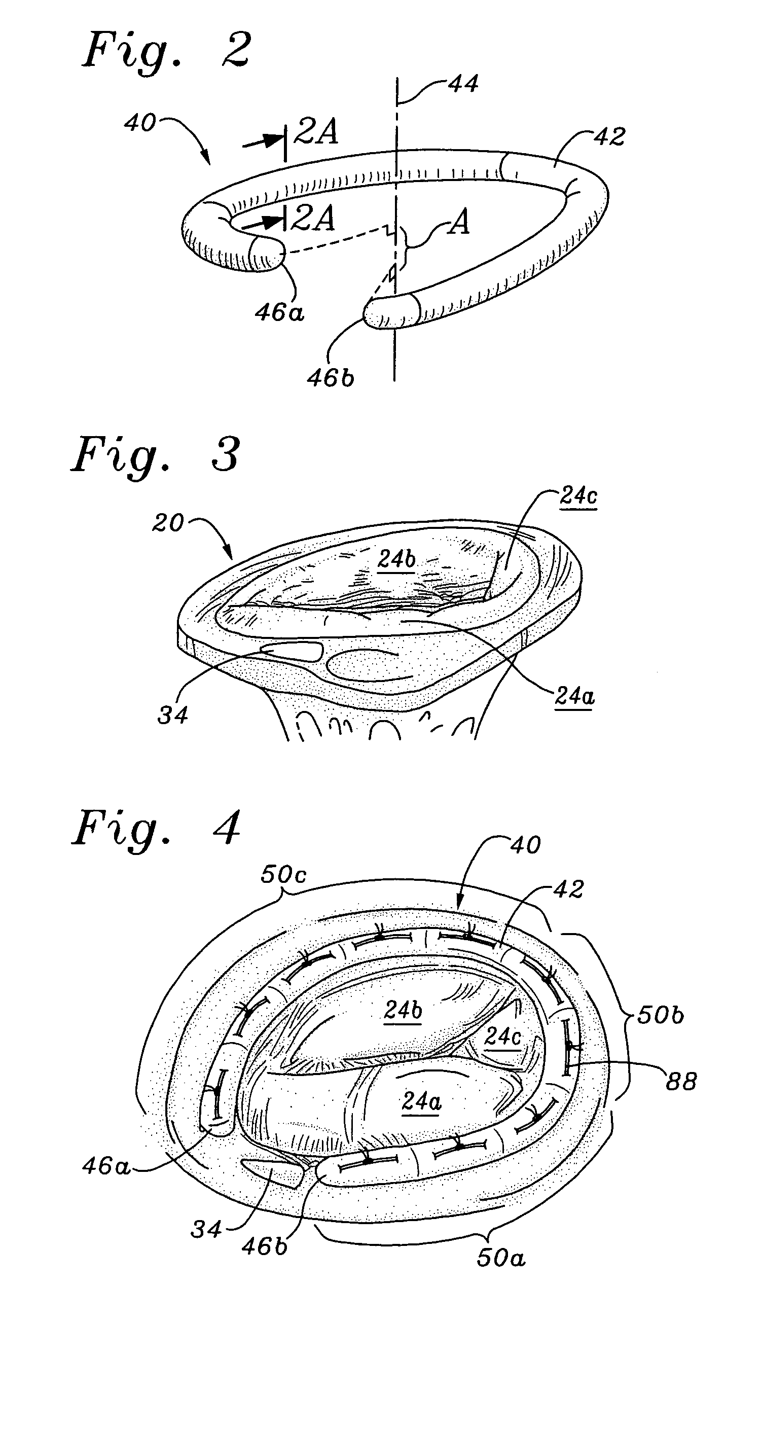
[0031]The present invention provides a non-planar or three-dimensional (3D) annuloplasty ring that is shaped to conform to a 3D annulus. Some studies show that the tricuspid valve has such a non-planar annulus, and thus the present invention is particularly suited for repair of that valve. Of course, other valves may in some patients have 3D annuluses, and the annuloplasty ring of the present invention may also have use in those locations, if desired by the surgeon. Of course, all annuloplasty rings are three-dimensional to some extent, as they have a cross-sectional thickness. In the context of the present invention, a non-planar or three-dimensional annuloplasty ring has a nominal cross-sectional centerline that assumes a three-dimensional shape, or in other words does not lie in a single plane. Likewise, the exemplary ring of the present invention, as well as other shapes that may benefit from the features embodied herein, has a non-circular peripheral shape, but is shown having ...


PUM


Abstract

An annuloplasty ring having a three-dimensional discontinuous form generally arranged about an axis with two free ends that are axially offset. The ring is particularly suited for repair of the tricuspid valve, and more closely conforms to the annulus shape. The ring is more flexible in bending about radially extending axes than about the central axis. The ring may have an inner structural support covered by a pliable sleeve and / or a fabric tube. The structural support may have a varying cross-section, such as a C-shaped cross-section in a mid-section between two free ends and a rectangular cross-section at the free ends. A deliver template having a mounting ring with about the same shape as the ring facilitates implant, and may be releasably attached to a delivery handle. The deliver template may include a plurality of cutting guides for releasably attaching the annuloplasty ring thereto while presenting maximum outer surface area of the ring. The template may have an outwardly-facing groove to receive and retain the ring.

Description

RELATED APPLICATIONS[0001]The present application is a continuation-in-part of U.S. application Ser. No. 09 / 941,406 filed Aug. 28, 2001, now U.S. Pat. No. 6,749,630. The present application is also a continuation-in-part of U.S. application Ser. No. 10 / 139,070, filed May 3, 2002, now U.S. Pat. No. 6,908,482.FIELD OF THE INVENTION[0002]The present invention relates generally to medical devices and particularly to a tricuspid annuloplasty ring and delivery template.BACKGROUND OF THE INVENTION[0003]In vertebrate animals, the heart is a hollow muscular organ having four pumping chambers: the left and right atria and the left and right ventricles, each provided with its own one-way valve. The natural heart valves are identified as the aortic, mitral (or bicuspid), tricuspid and pulmonary, and are each mounted in an annulus comprising dense fibrous rings attached either directly or indirectly to the atrial and ventricular muscle fibers.[0004]Heart valve disease is a widespread condition i...

Claims


Application Information

Patent Timeline
Patent Type & Authority Patents(United States)
IPC IPC(8): A61F2/24
CPCA61F2/2448A61F2/2466A61M25/001A61M25/0069A61F2/2445A61M25/0032A61M25/007A61M25/0071A61M25/0138A61M2025/0002A61M2025/0003A61M2025/0004A61M2025/0081
Inventor MCCARTHY, PATRICK M.RHEE, RICHARD S.SCHRECK, STEFAN G.
Owner EDWARDS LIFESCIENCES CORP
Learn More