Method and apparatus which enable high resolution particle beam profile measurement

a particle beam and profile technology, applied in the field of can solve the problems of grid drift, heat conduction along the bar, and additional complexity of measurement, and achieve the effects of reducing thermal effects, high-resolution particle beam profile measurement, and reducing thermal resistance away from the measurement poin

Inactive Publication Date: 2008-05-06
APPLIED MATERIALS INC
View PDF10 Cites 2 Cited by
  • Summary
  • Abstract
  • Description
  • Claims
  • Application Information

AI Technical Summary

Benefits of technology

[0013]The PSF for a metrology array for high resolution particle beam profile measurement has been improved by improving five major elements of the metrology array which impact the PSF of the array. While improvement in each of the five elements provides and improved PSF, a combination of all five of the elements provides an unexpected synergistic effect. The individual element improvements are as follows. 1) The metrology array comprises a plurality of slots rather than the previously-used square openings of the kind described above. The use of slotted openings in the metrology array reduces thermal effects because the thermal resistance away from the measurement point is lower. The lower thermal resistance is achieved because a lower percentage of the array substrate is removed than in a 1:1 square grid design, for example. 2) At least the upper 0.25 μm of thickness of the metrology array is comprised of a high-Z (high atomic number) material. Typically the upper 1 μm of thickness is essentially the high-Z material. In some instances, the entire substrate may be a high-Z material. A high-Z material is one in which the atomic number of the material is at least 45. The use of a high-Z material improves the opaqueness of the material to the particle beam, improves the scattering probability at the solid surfaces of the metrology array substrate, and provides better resolution in the backscattered image used to produce the beam shape profile. 3) The sidewalls on the slotted opening area of the metrology array substrate form an angle with a horizontal surface at the base of the metrology array substrate which is at least 75°, and which typically ranges from about 83° to about 89°. The steeper sidewall angles of the slotted opening in the metrology array substrate provide better contrast along the edge of the slot, because the edge transitions from 100% transmitting to 100% opaque is less distance. 4) The radius at the upper corner (knife edge) of a slotted opening ranges from about 1 nm to about 5 nm. The high Z material is applied to the substrate at an appropriate time in the manufacturing process, with respect to before or after slot formation, to minimize the radius. 5) The edge roughness at the upper corner (the knife edge) of each slot is less than 5 nm RMS, and typically ranges from about 1 nm RMS to about 3 nm RMS. The reduction in edge roughness from that typically present prior to the present invention also improves the contrast along the edge of the slot, so that there is less blur of the edge in the backscattered image used to produce the beam shape profile.
[0014]As previously discussed, a critical element for a metrology array is the width of the point-spread function (PSF). To accurately measure the profile of a particle beam, such as an electron beam, for example and not by way of limitation, the PSF should be at least three times smaller than the intrinsic blur of the electron beam. A typical particle beam blur for current day device feature sizes is in the range of 10 nm. The current apparatus (metrology arrays meeting the elemental requirements of the present invention) is capable of providing a PSF of about 3 nm or less.

Problems solved by technology

Additional complexity may be added to the measurement to obtain more accurate information.
A limiting factor of this design is the heat conduction from along the bar, due to interaction of the beam with the bar.
The limited availability of heat conduction changes the temperature at the measurement point, and thermal expansion at the measurement point causes the grid to drift.
When the grid drifts with respect to the particle beam, the measurement changes, making the measurements inaccurate.
This not only requires additional processing of the array, but also roughens the edges of apertures in the array, further increasing the PSF of the aperture.
This method of creating edges creates only a single edge and is not reliable in terms of a manufacturable, reliable means of edge creation.

Method used


Image

  • Method and apparatus which enable high resolution particle beam profile measurement
  • Method and apparatus which enable high resolution particle beam profile measurement
  • Method and apparatus which enable high resolution particle beam profile measurement

Examples


Embodiment Construction

[0023]As a preface to the detailed description, it should be noted that, as used in this specification and the appended claims, the singular forms “a”, “an”, and “the” include plural referents, unless the context clearly dictates otherwise.

[0024]Use of the term “about” herein indicates that the named variable may vary to ±10%.

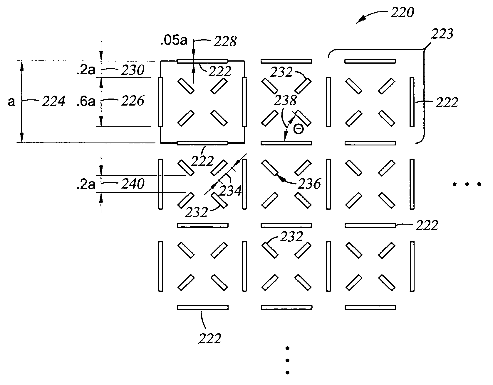
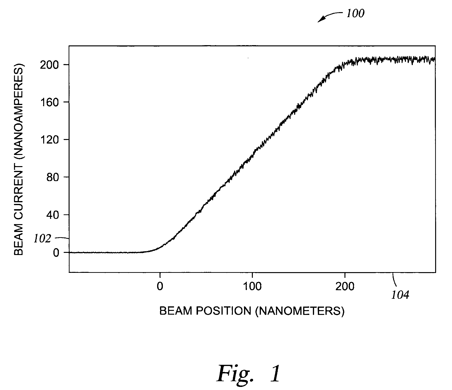
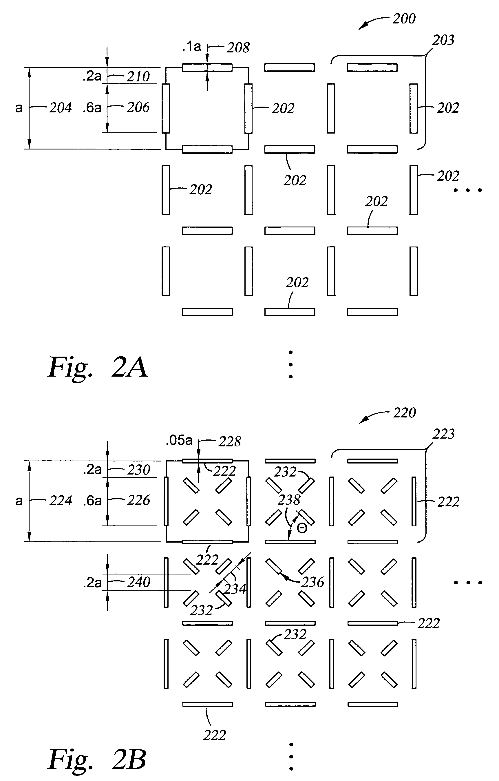
[0025]A substantial improvement in the measurement of a particle beam profile has been achieved using an improved metrology array over which the particle beam is scanned to obtain the beam profile. The point-spread function (PSF) of the a metrology array has been improved to provide better resolution of the particle beam profile. Although the embodiments described herein are with respect to an electron beam profile, one skilled in the art will see that the principles applied in the improvement of the metrology array are applicable to the improvement in measurement of beam profile with respect to any particle beam.

[0026]The metrology array has been improved by i...


PUM


Abstract

The PSF for a metrology array for high resolution particle beam profile measurement has been improved by improving five major elements of the metrology array. While improvement in each of the five elements provides and improved PSF, a combination of all five of the elements provides an unexpected synergistic effect. The individual elements include the use of a plurality of slots as apertures; use of a high-Z material in forming the array; employing sidewalls on the slotted opening apertures where the sidewall forms an angle with a horizontal surface at the base of the array which is at least 75°; employing a knife edge where the upper corner radius ranges from about 1 nm to about 5 nm; and providing a surface finish at the upper corner of each knife edge which is less than 5 nm RMS.

Description

FIELD OF THE INVENTION[0001]In general, the present invention relates to a method and apparatus which enable high resolution particle beam profile measurement.BRIEF DESCRIPTION OF THE BACKGROUND ART[0002]There is no admission that the background art disclosed in this section constitutes prior art.[0003]To be able to use a particle beam, such as an electron beam, by way of example and not by way of limitation, to create a pattern on a substrate, it is important to know the profile of the beam. The profile of the beam refers to the intensity of the beam as a function of position / location on the beam. Knowledge of the profile of the beam is innately valuable, because it shows how the particles, electrons for example, are being put down on the substrate, which determines how the pattern is formed. Since formation of the pattern on the substrate is carried out by making one little shape, and then another right next to it, and another little shape next to that, understanding at the very e...

Claims


Application Information

Patent Timeline
Patent Type & Authority Patents(United States)
IPC IPC(8): G21G5/00
CPCH01J37/265H01J2237/24507H01J2237/24542H01J2237/2826
Inventor SULLIVAN, JEFFREY S.
Owner APPLIED MATERIALS INC
Why Eureka
Try Eureka