Liquid crystal display with elastic ground contact on first side and multiple ground contacts on second side of drive circuit board

a technology of driving circuit board and ground contact, which is applied in static indicating devices, instruments, non-linear optics, etc., can solve the problems of generating various kinds of noise, and achieve the effects of reducing costs, simplifying construction process, and efficient control of noise generation

Inactive Publication Date: 2008-05-06
JAPAN DISPLAY WEST
View PDF7 Cites 27 Cited by
  • Summary
  • Abstract
  • Description
  • Claims
  • Application Information

AI Technical Summary

Benefits of technology

[0017]Considering these circumstances, the inventors discovered that various kinds of noise are generated mainly by electric connectors and in the vicinity thereof. On the other hand, the inventors presume that even though the electrical connectors are covered by a metal cover due to design restrictions, if at least one of the connectors is exposed and the ground line is formed within the vicinity of the exposed connector or very close to the metal cover, any noise generated by the connectors can be efficiently controlled, greatly facilitating machining of the earth connection means.
[0018]Consequently, the present invention aims to provide a liquid crystal display device equipped with a stable ground line formed by a simple machining process for the purpose of eliminating noise interference.
[0030]In the liquid crystal display of the present invention, since the earth contacts reside within the vicinity of the liquid crystal drive circuit board where the connectors are disposed, the earth contacts are connected to the electronic parts and the like that are mounted on the liquid crystal drive circuit board to form the ground line, thereby efficiently controlling the generation of noise. Further, since the earth terminals of the liquid crystal display of the present invention reside on the peripheral edge of the cutout portion of the metal cover where the electric connectors are exposed, the earth terminals can be simultaneously set up together with the cutout portion, thereby simplifying the construction process and reducing costs.
[0031]Furthermore, in the liquid crystal display of the present invention, the convex protrusions are also formed on the back case and made to come into contact with the earth contacts provided on the circuit board, so that the earth terminals in effect thrust the circuit board downward while they come into elastic contact with the earth contacts, while on the other hand, the multiple convex protrusions on the back case push up the circuit board. Consequently, good contact is established between the earth terminals and the earth contacts even if vibration or the like occurs when the liquid crystal display is in use, likewise providing stable support to the liquid crystal drive circuit board.

Problems solved by technology

Considering these circumstances, the inventors discovered that various kinds of noise are generated mainly by electric connectors and in the vicinity thereof.

Method used


Image

  • Liquid crystal display with elastic ground contact on first side and multiple ground contacts on second side of drive circuit board
  • Liquid crystal display with elastic ground contact on first side and multiple ground contacts on second side of drive circuit board
  • Liquid crystal display with elastic ground contact on first side and multiple ground contacts on second side of drive circuit board

Examples


Embodiment Construction

[0037]The embodiments of the present invention will hereafter be described with reference to the accompanying drawings.

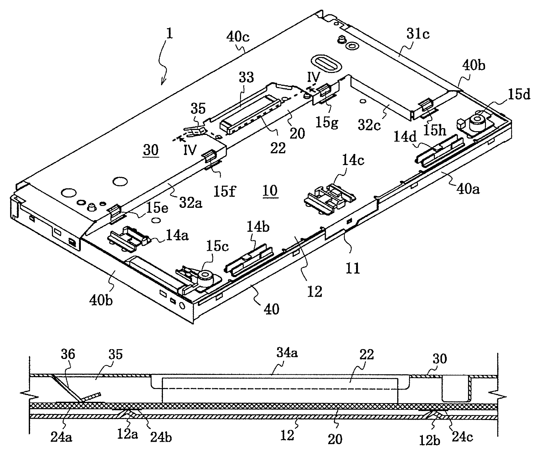
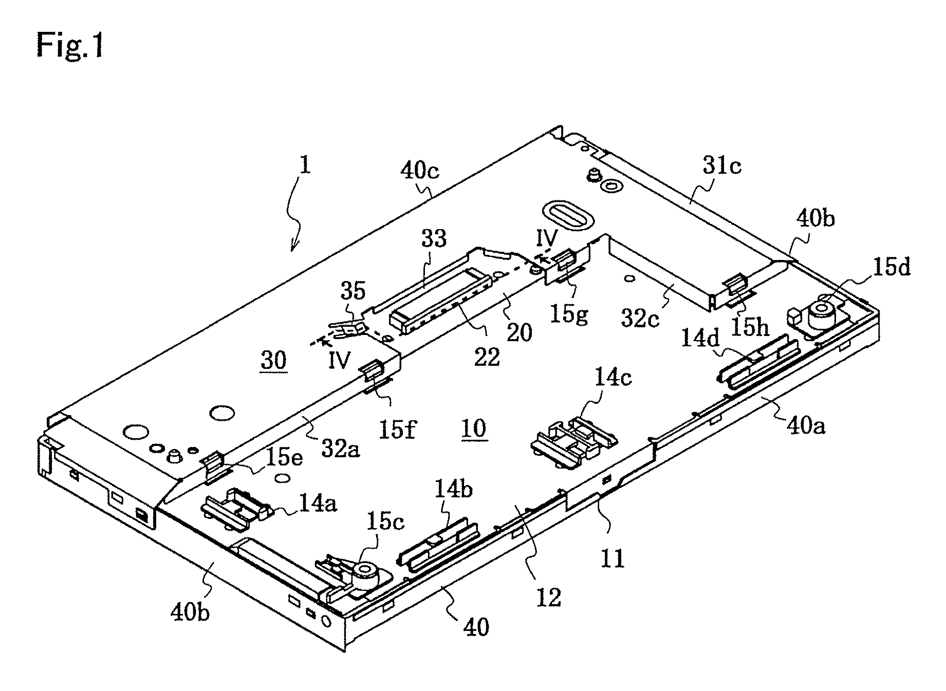
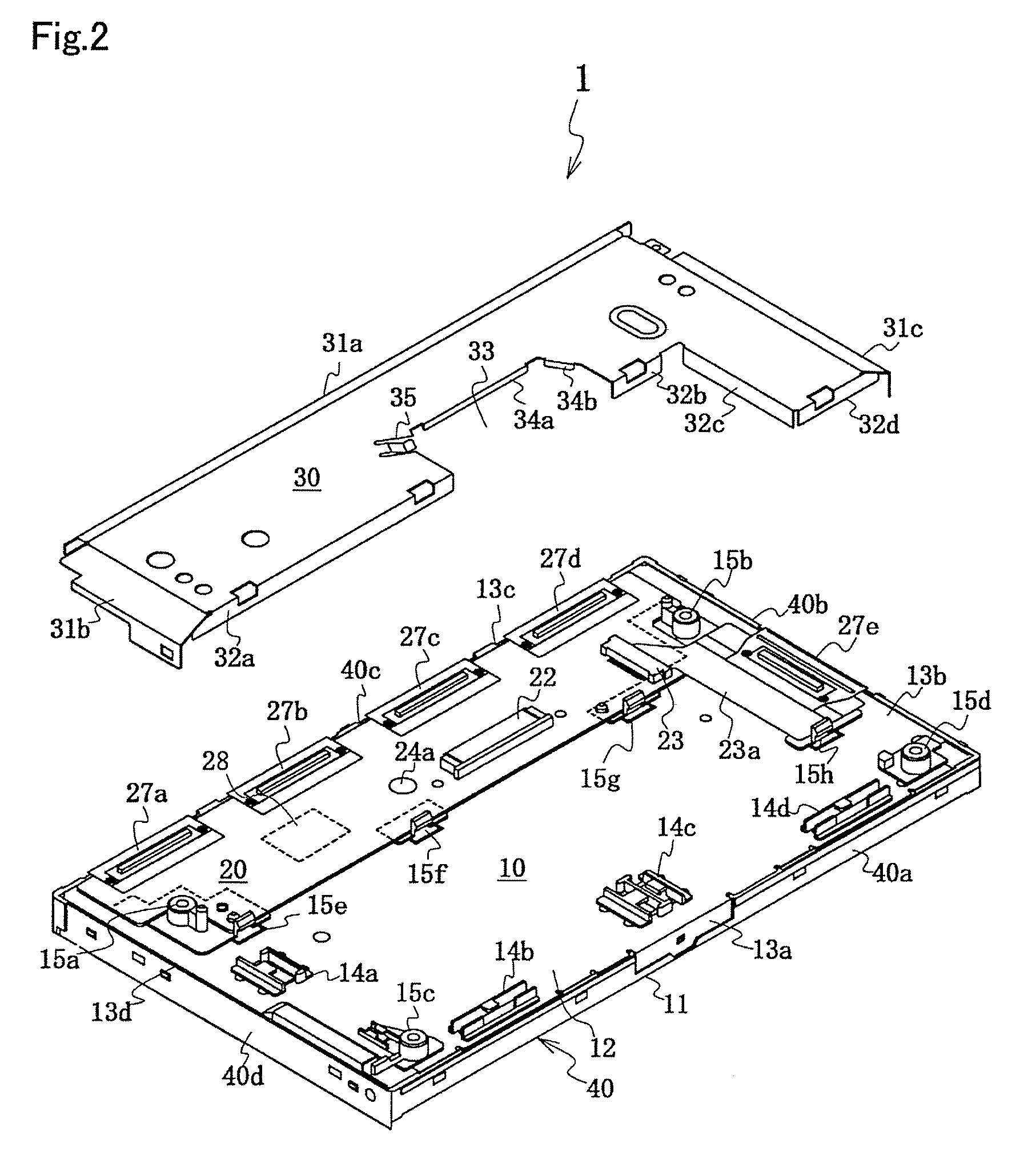
[0038]FIG. 1 shows an embodiment of the liquid crystal display of the present invention, and is the perspective view of the liquid crystal display viewed from the back, while FIG. 2 is the exploded perspective view of the liquid crystal display shown in FIG. 1 in which the metallic cover (back lid) of the display is not in place. FIG. 3 is a plane view of the circuit board of the liquid crystal display of FIG. 1, while FIG. 4 is an enlarged sectional view of the line marked IV-IV in FIG. 1.

[0039]The liquid crystal display 1 comprises a substantially rectangular liquid crystal module 10, a liquid crystal drive circuit board 20 mounted on the backside of the liquid crystal module and electrically connected to and extending from one peripheral edge of the liquid crystal module 10 for a predetermined length toward a central area, which is about ⅓ to ½ the distance to th...


PUM

PropertyMeasurementUnit
lengthaaaaaaaaaa
heightaaaaaaaaaa
shapeaaaaaaaaaa

Abstract

A liquid crystal display comprises a liquid crystal module (10) having a predetermined shape and having a back side covered with a metal back case (12); a liquid crystal drive circuit board (20) electrically connected at one side of the liquid crystal module (10), extending toward the central portion from the one side by predetermined length, having an electric connector (22) disposed on one side of the circuit board (20), and mounted on the metal back case (12); and a metal cover (30) having a cutout (33) large enough to expose the electric connector (22) and covering the circuit board (20). An earth terminal (36) is provided at one edge of the cutout (33) and is brought into elastic contact with an earth contact (24a) provided on one side of the circuit board (20) when the circuit board (20) is covered with the metal cover (30). With this constitution, a stable ground line is formed in the display by a simple machining to avoid noise interference.

Description

[0001]This application is a national stage entry under 35 U.S.C. § 371 of PCT / JP04 / 00819, filed Jan. 29, 2004, (designating the U.S.; and which was published in Japanese in WO 2004 / 068229 on Aug. 12, 2004), which claims the benefit of Japanese Patent Application No. 2003-024202, filed Jan. 31, 2003, the contents of which are incorporated herein by reference.BACKGROUND OF THE INVENTION[0002]1. Field of the Invention[0003]The present invention relates to a small-sized liquid crystal display device particularly suitable for PDAs, car navigation systems, laptop personal computers, small-sized television sets and the like, and particularly to a liquid crystal display device in which a stable ground line is formed therein the display panel to eliminate noise interference.[0004]2. Prior Art[0005]In recent years, liquid crystal display devices have come to be widely used in various kinds of instruments such as PDAs, car navigation systems, laptop personal computers, small-sized television s...

Claims


Application Information

Patent Timeline
Patent Type & Authority Patents(United States)
IPC IPC(8): G02F1/1333G02F1/13G02F1/1345G09G3/36
CPCG02F1/13452G09G3/3611G02F1/133308G09G2330/02G09G2320/02G02F2001/133314G02F1/133314G02F1/1333
Inventor OKAMOTO, HIROAKINISHIURA, MASAYOSHIKISHI, HIDEAKITANAKA, KATSUMI
Owner JAPAN DISPLAY WEST
Why Eureka
Try Eureka