
Intra-premises wireless broadband service using lumped and distributed wireless radiation from cable source input

a wireless broadband and cable source technology, applied in the field of intra-premises wireless broadband service using lumped and distributed wireless radiation from cable source input, can solve the problems of affecting the service provider's ability to provide this added wiring, affecting the service, and affecting the service provider's ability to provide the service. cost and other issues to achieve the effect of cost-effectiveness

Inactive Publication Date: 2008-05-06
AMERICAN TELEPHONE & TELEGRAPH CO
View PDF19 Cites 17 Cited by
  • Summary
  • Abstract
  • Description
  • Claims
  • Application Information

AI Technical Summary

Benefits of technology

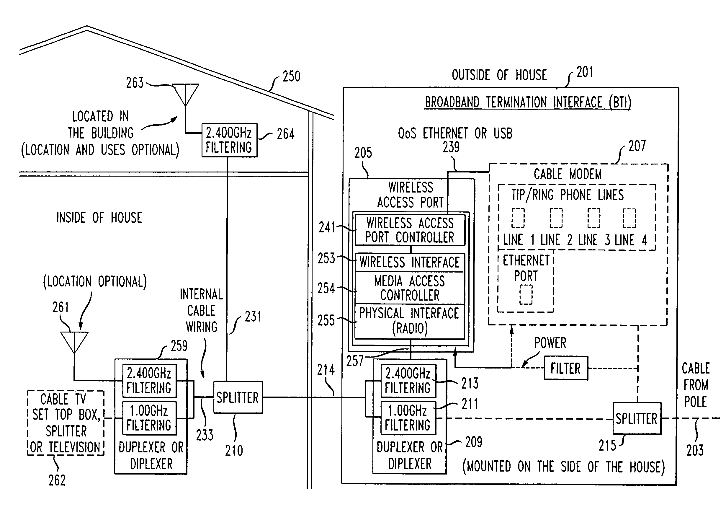
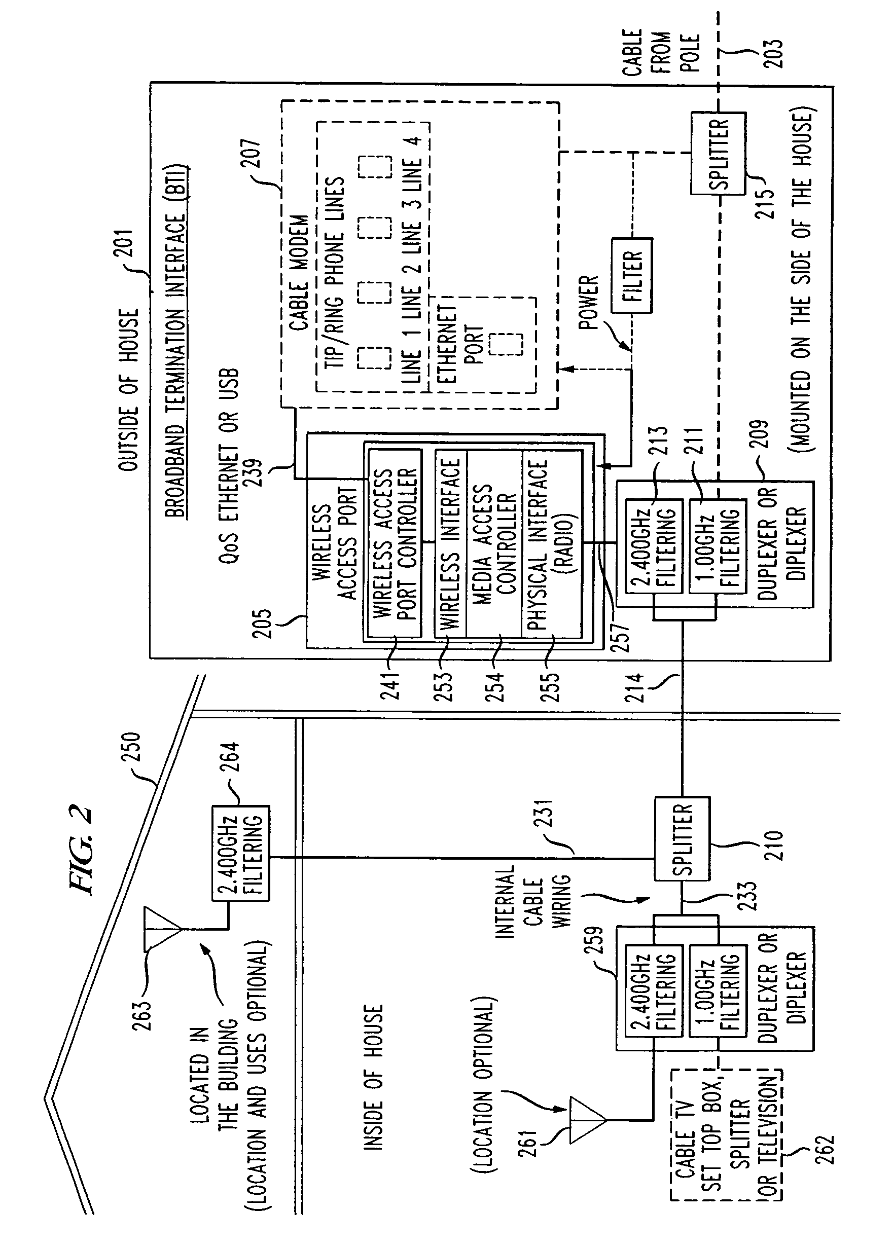
"The patent describes a way to distribute broadband services throughout a premises without adding any new wiring. This is done by using existing coaxial cable and wireless transmission throughout the premises. A single wireless access node is used to transport the broadband services via the existing coax cabling. This method provides cost-effective distribution of broadband services within the premises. The broadband services are connected to a broadband interface unit, which then transmits the signals to an antenna located within the premises. The antenna then wirelessly radiates the signals to client devices. This system provides broadband data, voice, and multimedia signals to applications by a wireless signal as distinguished from the signals supplied by the cable and internal wiring that are directly connected to the consumer devices. The system uses a built-in or adjunct wireless transceiver to convert the broadband data into a RF signal for transmission. The RF signal is then coupled to the in-premises cabling, and a diplexer is used to connect the RF signal containing the broadband data, multimedia, and voice signals to a signal radiation device (e.g. an RF antenna or leaking from the coaxial cable) which radiates the signal to the immediate surrounding location. The system can also radiate application generated signals back through the antenna and diplexer for transmission through the in-premises cable to the broadband interface unit and back to the cable system."

Problems solved by technology

This often requires added wiring to be routed within the premises at an added expense that may result in some potential customers not accepting such service when offered or in a large expense to the service provider.
To provide this added wiring is an expensive and extensive undertaking since the added wiring must traverse the various interior regions of the house is order to connect to the varied devices capable of broadband services.
When the transceiver is located inside the structure, no additional wiring is needed, but wireless radiation to various sections of the premises is often impeded by internal structural elements of the premises.
But by locating the device on the outside of the premises, the outer wall structure becomes an added barrier to adequate radiation to many locations within the premises.
Hence, receiving a signal from a single fixed wireless transmitter, through structure within or without the premises, results in an attenuated signal with inferior signal quality at many internal locations.

Method used


Image

  • Intra-premises wireless broadband service using lumped and distributed wireless radiation from cable source input
  • Intra-premises wireless broadband service using lumped and distributed wireless radiation from cable source input
  • Intra-premises wireless broadband service using lumped and distributed wireless radiation from cable source input

Examples


Embodiment Construction

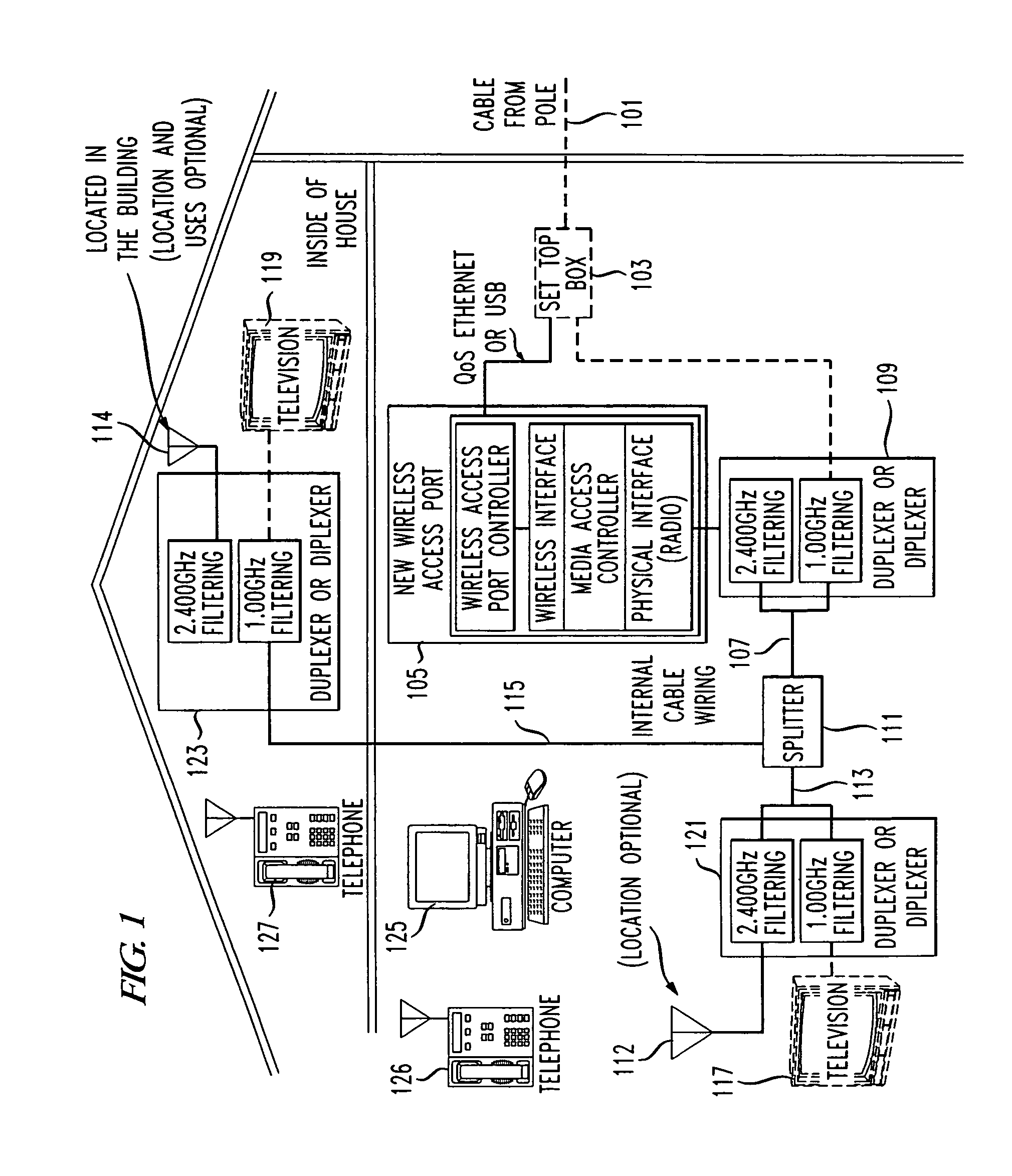
[0013]A typical exemplary broadband distribution architecture for delivery of broadband services in residential premises, as shown in the FIG. 1, receives broadband input, including multimedia, data and voice, via cable link 101. This cable link is shown connected to a set top box 103 within the premises. Device 103 converts the incoming RF frequencies containing the broadband and broadcast signals to the format necessary to accommodate the devices to be serviced within the premises. Set top boxes and cable modems are a well-known item and further discussion of their operation is not believed necessary.

[0014]A broadband wireless device 105 is attached to the cable modem section of device 103 via a data access port, which in FIG. 1 is included within the cable modem section of device 103. Such a connection may alternatively comprise a USB (Universal Serial Bus), an Ethernet connection or similar connection port used as a direct connection. The connection port is capable of bi-directi...


PUM


Abstract

A premises, connected to receive broadband service(s) and also connected to a cable system, is provided with a broadband interface which connects to in-premises cabling which is coupled to consumer receivers such as a television sets, PDAs, laptops. Connected to the broadband interface is an adjunct device which channels broadband, data and voice signals supplied to an in-premises wireless system as distinguished from the signals supplied to the cable connected consumer receivers. The adjunct device formats the broadband and voice signals or any broadband service into packet format suitable for signal radiation and couples them to the in-premises coax cabling, via a diplexer, at a first selected location. At a second cable location a second diplexer, connected to the cable, separates the broadband, data and voice signals and couples them to a signal radiation device (i.e., an RF antenna or leaky coaxial cable) which radiates the signal to the immediate surrounding location. Various devices, near to the second cable location for specific services, receive the wireless signals (i.e., broadband, data and voice) from the radiating antenna.

Description

CROSS-REFERENCE TO RELATED APPLICATIONS[0001]This application is a continuation of, claims priority to, and incorporates herein by reference in its entirety, U.S. patent application Ser. No. 09 / 678,522, filed 3 Oct. 2000 now U.S. Pat. No. 6,751,441.FIELD OF THE INVENTION[0002]This invention relates to provision of broadband services within premises supplied with cable service such as a small office or a residence. It is specifically concerned with wireless distribution of these broadband services within the premises. A particular variant of this distribution system concerns the use of existing coaxial cable within the premises for distribution of these services by wireless radiation and the modes of distributing this radiation within the premises.BACKGROUND OF THE INVENTION[0003]Broadband communication systems (Le. cable systems) provide the capability of delivering various bundles of voice, video, and data services to premises. Once delivered to a premises it must be distributed to...

Claims


Application Information

Patent Timeline
Patent Type & Authority Patents(United States)
IPC IPC(8): H04M9/00H04B3/36H04L12/28
CPCH04B7/15H04L12/2801H04N21/2143H04L12/2838H04L12/2803H04N7/104H04N21/42676
Inventor MURRAY, JOHN F.RICE, CHRISTOPHER W.WORSTELL, HARRY R.
Owner AMERICAN TELEPHONE & TELEGRAPH CO
Learn More