Piston engine with integrated balance shafts

a technology of balance shaft and piston engine, which is applied in the field of piston engines, can solve the problems of no longer falsification, and achieve the effect of minimizing the structural weakening of the crankcas

Inactive Publication Date: 2008-05-13
MAGNA DRIVETRAIN
View PDF21 Cites 4 Cited by
  • Summary
  • Abstract
  • Description
  • Claims
  • Application Information

AI Technical Summary

Benefits of technology

[0006]It is the underlying object of the invention to set forth a way for the precise setting of the gear engagement with the simplest possible installation also for balance shafts integrated in the housing. In accordance with the invention, this consists of the characterizing features a) and b) of the independent claim. The drive by means of gears allows the unit to be attached from the outside with a few hand movements, provided a setting of the tooth clearance from outside is successful. This is successful due to the planar joint faces being able to be pushed onto one another. The window into the interior of the crankcase only needs to be a little larger than the gear, whereby the structural weakening of the crankcase can be minimized.
[0008]In a preferred arrangement, the joint face encloses an obtuse angle with the connection straight line of the axes of the crankshaft and the balance shaft in a section imagined normally to the crankshaft axis. The angle may not be a right angle, because a displacement of the balance shaft unit would then not effect any change in the tooth clearance. The obtuse angle, however, results in a “ratio”, whereby the tooth clearance can be set very precisely with a large displacement of the balance shaft unit and is also no longer falsified when the screws are tightened after the setting. Furthermore, the joint faces are preferably parallel to the plane of symmetry of the crankcase; this moreover simplifies the processing.
[0009]In a further development of the invention, at least one sliding guide is provided in the joint faces of the crankcase and of the housing of the balance shaft unit and permits a displacement in a plane normal to the crankshaft. This facilitates the setting and provides the assurance that the axes of the two gears meshing with one another remain parallel. A clean engagement over the whole tooth width is thus also still ensured additionally to the precisely set rotational flank clearance.
[0010]The sliding guide preferably consists of a straight groove in the sliding direction in one of the two joint faces and of a key let into the other joint face. This combines high precision with simple production.
[0012]A more sophisticated aspect of the invention consists of the gear of the balance shaft being arranged at its center. The gear seated on the crankshaft is then accordingly also in the center. With a central drive, the characteristic frequency of the torsion of the balance shaft is higher and the balance shaft unit can be arranged at the longitudinal center of the engine, close to its center of gravity. The selection of the position of the balance shaft units such that the gear of the balance shaft unit and the intermediate gear of the second balance shaft unit mesh with the gear seated on the crankshaft at positions offset by 180 degrees to one another has similarly favorable effects.

Problems solved by technology

The obtuse angle, however, results in a “ratio”, whereby the tooth clearance can be set very precisely with a large displacement of the balance shaft unit and is also no longer falsified when the screws are tightened after the setting.

Method used


Image

  • Piston engine with integrated balance shafts
  • Piston engine with integrated balance shafts
  • Piston engine with integrated balance shafts

Examples


Embodiment Construction

[0024]The following description of the preferred embodiment is merely exemplary in nature and is in no way intended to limit the invention, its application, or uses.

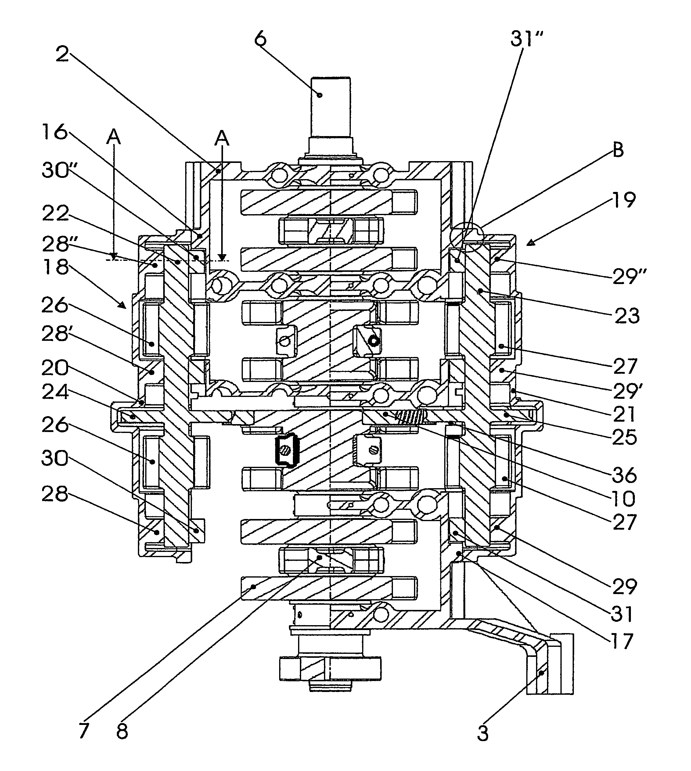
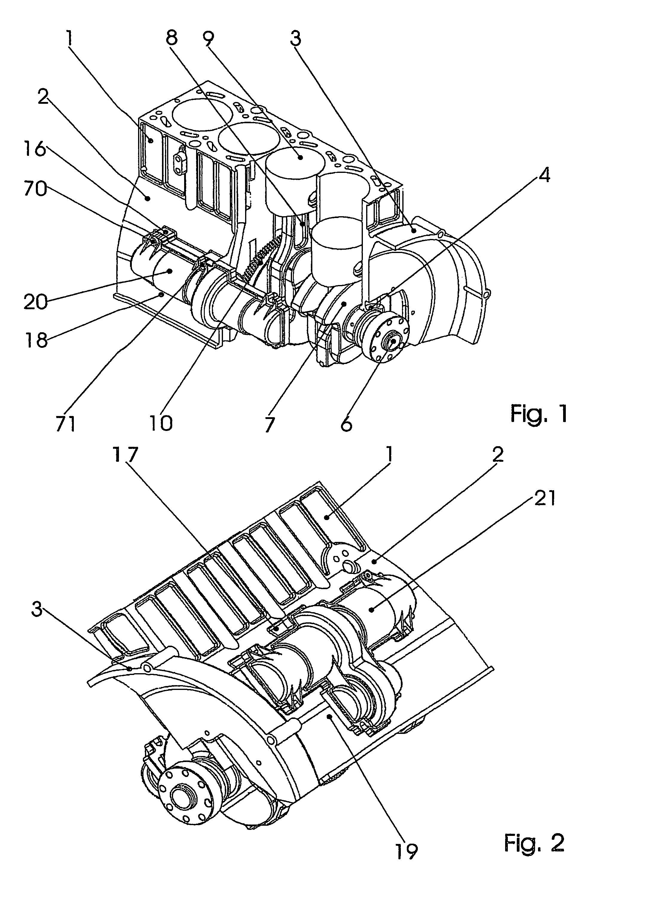
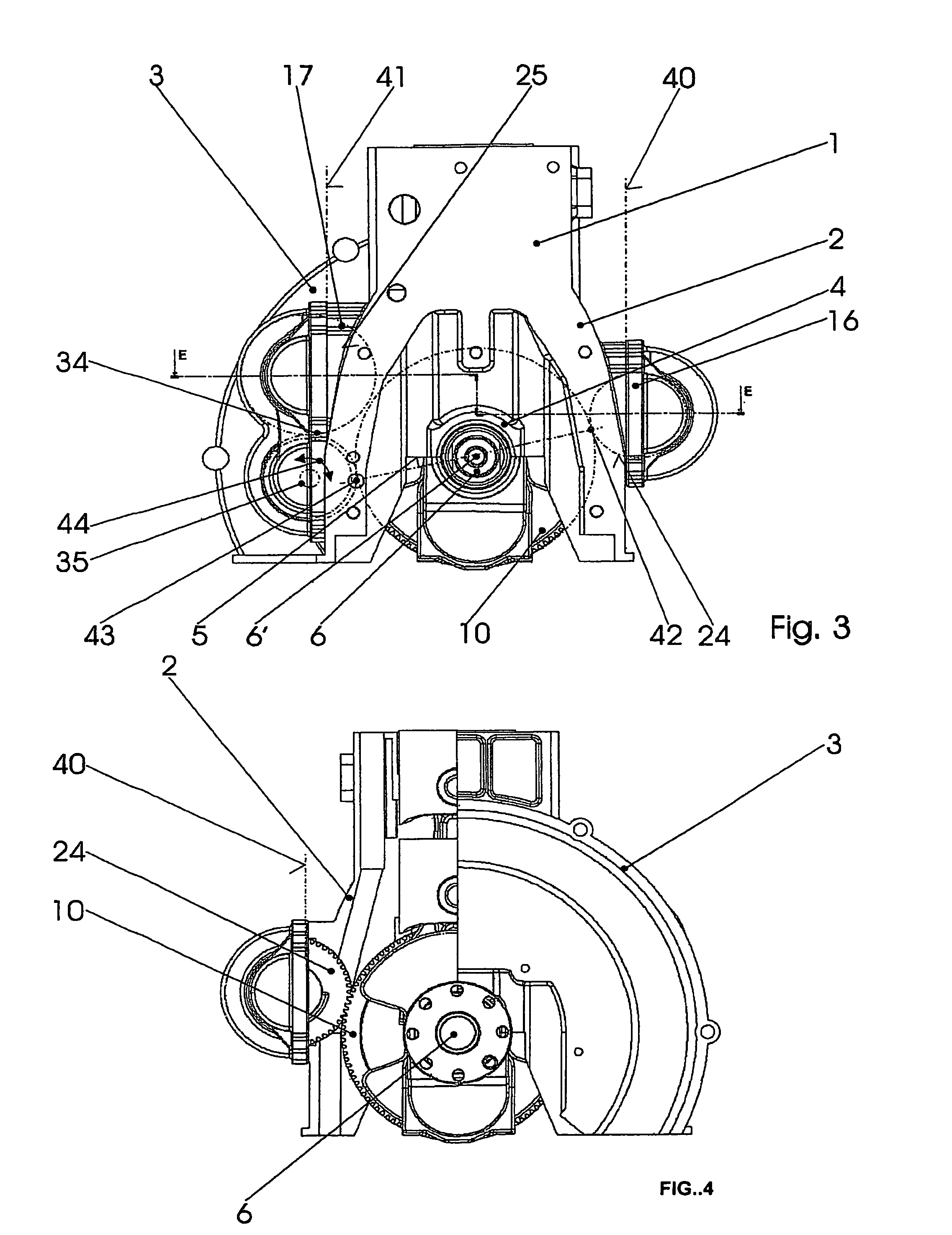
[0025]In FIGS. 1 to 4, a four-cylinder internal combustion engine is shown in different views. In all of them, the cylinder block is designated with 1, the crankcase in sum with 2 and the flywheel housing with 3, although they are made integrally here. Five crankshaft bearings 4 are provided in the crankcase 2 and their bearing halves disposed over a joint plane 5 are in the crankcase 2. A crankshaft 6 (whose central axis is designated with 6′ in FIG. 3) is journaled in said crankshaft bearings and con rods 8 connected at the other end to pistons 9 are between their crank webs 7. A gear 10 is rotationally fixedly arranged between one of the crankshaft bearings 4 and a crank web 7 and serves the drive of the balance shafts.

[0026]A flange 16 is cast on the crankcase 2 considered from the rear (from the flywheel housing 3) ...


PUM

PropertyMeasurementUnit
centering angleaaaaaaaaaa
obtuse angleaaaaaaaaaa
symmetryaaaaaaaaaa

Abstract

A piston engine with a compensation shaft unit, wherein a window surrounded by a flange is provided on the crankcase thereof. The flange forms a separating surface to which the housing of the compensation shaft unit is fixed by means of screws. In order to ensure clean, toothed-wheel engagement for the compensation shafts, which are integrated into the housing, and easy assembly, the compensation shaft is provided with a toothed wheel, which protrudes through the window inside the crankcase, and which is driven by a toothed wheel, which is arranged on the crankshaft, and the housing of the compensation shaft unit has a separating surface, which can be displaced in order to adjust the amount of engagement clearance on the separating surface of the crankcase before the screws are tightened.

Description

CROSS-REFERENCE TO RELATED APPLICATIONS[0001]This application is a National Stage of International Application No. PCT / AT2004 / 000425, filed Dec. 2, 2004, and which claims priority to Austrian Utility Model No. GM 854 / 2003, filed Dec. 2, 2003. The disclosures of these applications are incorporated herein by reference.FIELD OF THE INVENTION[0002]The invention relates to a piston engine comprising at least one balance shaft unit in whose crankcase a crankshaft is supported and at whose crankcase a window surrounded by a flange is provided at the side, with the flange forming a joint face to which the housing of the balance shaft unit is fastened by means of screws, with a balance shaft being supported in said housing. The piston engine is primarily considered as an internal combustion engine.BACKGROUND OF THE INVENTION[0003]With the internal combustion engines customary at the moment with pairwise balance shafts, a unit containing both balance shafts is connected to the crankshaft bear...

Claims


Application Information

Patent Timeline
Patent Type & Authority Patents(United States)
IPC IPC(8): F02B75/06B23P11/00B60S11/00B62D25/20F02B67/04F02B77/14F02F7/00F16F15/26
CPCB23P11/00F02B67/04F16F15/264Y10T74/2184F02F7/0046F02B77/14F16F15/26F16F15/22
Inventor MESSING, MICHAELMARZY, ROLANDPENZINGER, RONALD
Owner MAGNA DRIVETRAIN
Why Eureka
Try Eureka