Rotating gantry of particle beam therapy system

a technology of rotating gantry and beam therapy, which is applied in the direction of fluid actuated brakes, instruments, therapy, etc., can solve the problems of rigidity of the gantry barrel and the need for positioning of the patient body, and achieve the effect of quick discharge, reduced braking time of the rotating gantry, and increased brake respons

Active Publication Date: 2008-05-13
HITACHI LTD +1
View PDF23 Cites 224 Cited by
  • Summary
  • Abstract
  • Description
  • Claims
  • Application Information

AI Technical Summary

Benefits of technology

[0007]Against that background, a rotating gantry has recently been proposed in which the gantry barrel connecting the front ring and the rear ring has a cylinder structure. With such a rotating gantry, the rigidity of the gantry barrel can be increased and the variation of the isocenter accuracy can be suppressed to about 1 mm.
[0008]Although the proposed rotating gantry is able to improve the irradiation accuracy by increasing the rigidity of the gantry barrel by employing the cylinder structure, its weight is increased in comparison with the above-mentioned known rotating gantry including the gantry barrel made up of the plurality of braces and the reinforcing members of the truss structure. As a result, the inertial moment of the rotating gantry is increased and so is an emergency stop angle (i.e., an angle through which the rotating gantry is rotated from a time when emergency stop is instructed in a state rotating at the set speed to a time when a braking force from a brake is applied at 100%). The emergency stop is performed, for example, when the irradiation device is about to contact a treatment couch on which the patient is lying, etc. with malfunction of the rotating gantry, or when the condition of the patient is abruptly changed. From the viewpoint of safety, therefore, the emergency stop angle is preferably held comparable to that of the rotating gantry having the rigidity not yet increased. To that end, a response of the brake for applying the braking force to the rotating gantry has to be improved.
[0011]An object of the present invention is to provide a rotating gantry of a particle beam therapy system, which can actuate braking in a shorter time.
[0013]In the rotating gantry of the present invention, the solenoid valve for supplying (sealing) and discharging air to and from the brake with opening and closing operations is supported by the solenoid valve support member mounted to the roller support member, whereby the solenoid valve can be positioned just near the brake. Therefore, an amount of air sealed in a line connecting the brake and the solenoid valve can be reduced, and the sealed air can be more quickly discharged from the brake. As a result, a response of the brake can be increased and a braking time of the rotating gantry can be cut. In particular, even when the rotating gantry has a larger mass due to rigidity increased for an improvement of irradiation accuracy, it is possible to brake and stop the rotating gantry in a shorter time.
[0014]According to the present invention, the rotating gantry of the particle beam therapy system can be braked and stopped in a shorter time.

Problems solved by technology

In the known rotating gantry described above, although the reinforcing members of the truss structure are provided, the rigidity of the gantry barrel is not sufficient and three-dimensional swivel accuracy of the irradiation position during the irradiation of the ion beam from the irradiation device to the isocenter (i.e., isocenter accuracy) has a variation of about several millimeters with the rotation of the rotating gantry.
Such a variation causes the problem that, prior to starting the irradiation for treatment, a lot of time is required for positioning of the patient body depending on an irradiation angle.

Method used


Image

  • Rotating gantry of particle beam therapy system
  • Rotating gantry of particle beam therapy system
  • Rotating gantry of particle beam therapy system

Examples


Embodiment Construction

[0024]One preferred embodiment of a rotating gantry of a particle beam therapy system will be described below with reference to the drawings.

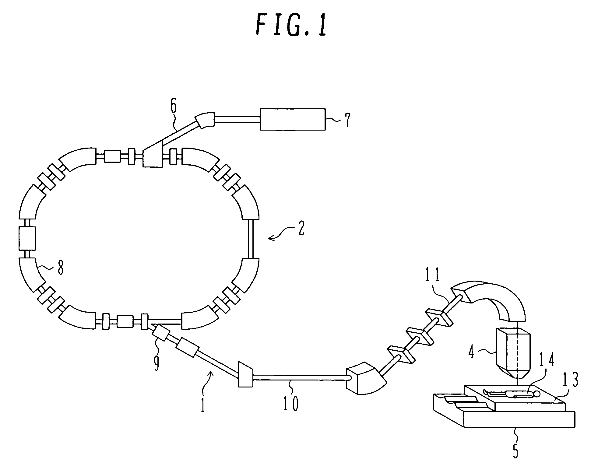
[0025]The particle beam therapy system to which the rotating gantry according to the preferred embodiment is applied will be described below with reference to FIG. 1. The particle beam therapy system 1 comprises an ion beam generator 2, a rotating gantry 3 (see FIGS. 2 and 3), an ion beam irradiation device (hereinafter referred to simply as an “irradiation device”) 4, and a treatment bench 5. The particle beam therapy system 1 is practically used as a cancer treatment system. The ion beam generator 2 includes an ion source (not shown), a pre-stage accelerator 7, and a synchrotron 8. Ions (e.g., protons or carbon ions) generated in the ion source are accelerated by the pre-stage accelerator 7 (e.g., a linear accelerator). The accelerated ion beam is introduced from the pre-stage accelerator 7 to the synchrotron 8 through a low-energy beam line ...


PUM


Abstract

A rotating gantry includes a link frame for supporting a plurality of rollers which rotatably support the rotating gantry, a brake for releasing a braking force applied to at least one of the rollers upon supply of air and applying the braking force to the one roller upon discharge of air, and a solenoid valve for sealing the supplied air in the brake when closed, and discharging the air from the brake when opened. The solenoid valve is supported by a solenoid valve support member mounted to the link frame such that the solenoid valve is positioned just near the brake. The rotating gantry can be more quickly braked and stopped while maintaining high irradiation accuracy.

Description

BACKGROUND OF THE INVENTION[0001]1. Field of the Invention[0002]The present invention relates to a rotating gantry of a particle beam therapy system, and more particularly to a rotating gantry suitable for use in a particle beam therapy system for irradiating an ion beam, such as a proton or carbon ion beam, to an affected part of the patient body for treatment.[0003]2. Description of the Related Art[0004]There is known a therapy method of setting an isocenter (irradiation target center) to an affected part of the patient body, e.g., a cancer, and irradiating an ion beam, such as a proton or carbon ion beam, to the affected part. A particle beam therapy system for use with that therapy method comprises, for example, an ion beam generator, a beam line, and an irradiation device installed in a rotating gantry. The ion beam accelerated in the ion beam generator reaches the irradiation device through the beam line and is irradiated to the affected part of the patient body from the irrad...

Claims


Application Information

Patent Timeline
Patent Type & Authority Patents(United States)
IPC IPC(8): A61N5/01A61N5/10
CPCA61N5/10A61N5/1081F16D55/40A61N2005/1087F16D2121/12
Inventor YAMASHITA, TSUTOMUKANEKO, SHIGEJIMURAMATSU, YUTAKASAGA, HIROSHI
Owner HITACHI LTD
Why Eureka
Try Eureka