Pivoting assembly of a hand tool

a technology of hand tools and pivotal parts, which is applied in the direction of manufacturing tools, couplings, mechanical devices, etc., can solve the problems of difficult positioning of pivotal parts, inefficiency of operation, and complicated structure, and achieve the improvement of defects in the prior art, the effect of reducing the thickness and complexity

Active Publication Date: 2008-05-20
HSIEH CHIH CHING
View PDF7 Cites 21 Cited by
  • Summary
  • Abstract
  • Description
  • Claims
  • Application Information

AI Technical Summary

Benefits of technology

[0005]Accordingly, the primary object of the present invention is to provide a pivoting assembly of a hand tool by which a driving portion of a hand tool is pivotally rotated with respect to the handle of the hand tool so as to improve the defects in the prior art, such as complicated structure, greater thickness and difficult in assembly and manufacturing.

Problems solved by technology

However the driving portion is retained to the handle, that is, the driving portion cannot rotate with respect to the handle so that if the work environment is not suitable for locating the spanner.
The operator will feel uneasy in operation and the operation is inefficiency.
However the pivotal portion has a complicated structure and it is difficult to position the pivotal portion.
Thereby it is impractical.
Firstly, the pivotal portion between the driving portion and the handle is too large to be stored.
Thereby the structure of the pivotal portion is complicated so that the cost is high and the manufacturing efficiency is low.
Furthermore, the operations for buckling and rotating the pivotal portion are inconvenient.

Method used


Image

  • Pivoting assembly of a hand tool
  • Pivoting assembly of a hand tool
  • Pivoting assembly of a hand tool

Examples


Embodiment Construction

[0022]In order that those skilled in the art can further understand the present invention, a description will be described in the following in details. However, these descriptions and the appended drawings are only used to cause those skilled in the art to understand the objects, features, and characteristics of the present invention, but not to be used to confine the scope and spirit of the present invention defined in the appended claims.

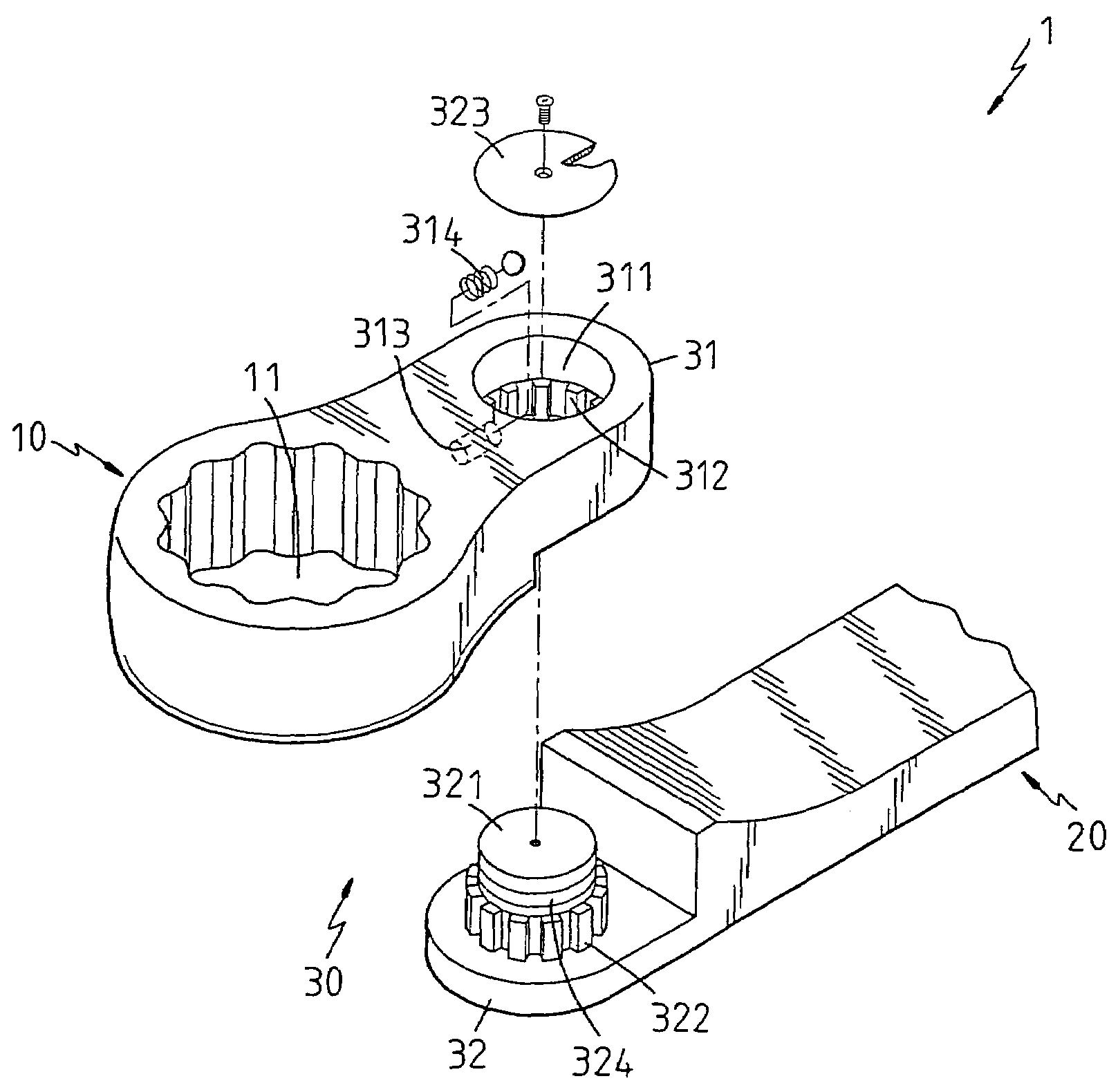
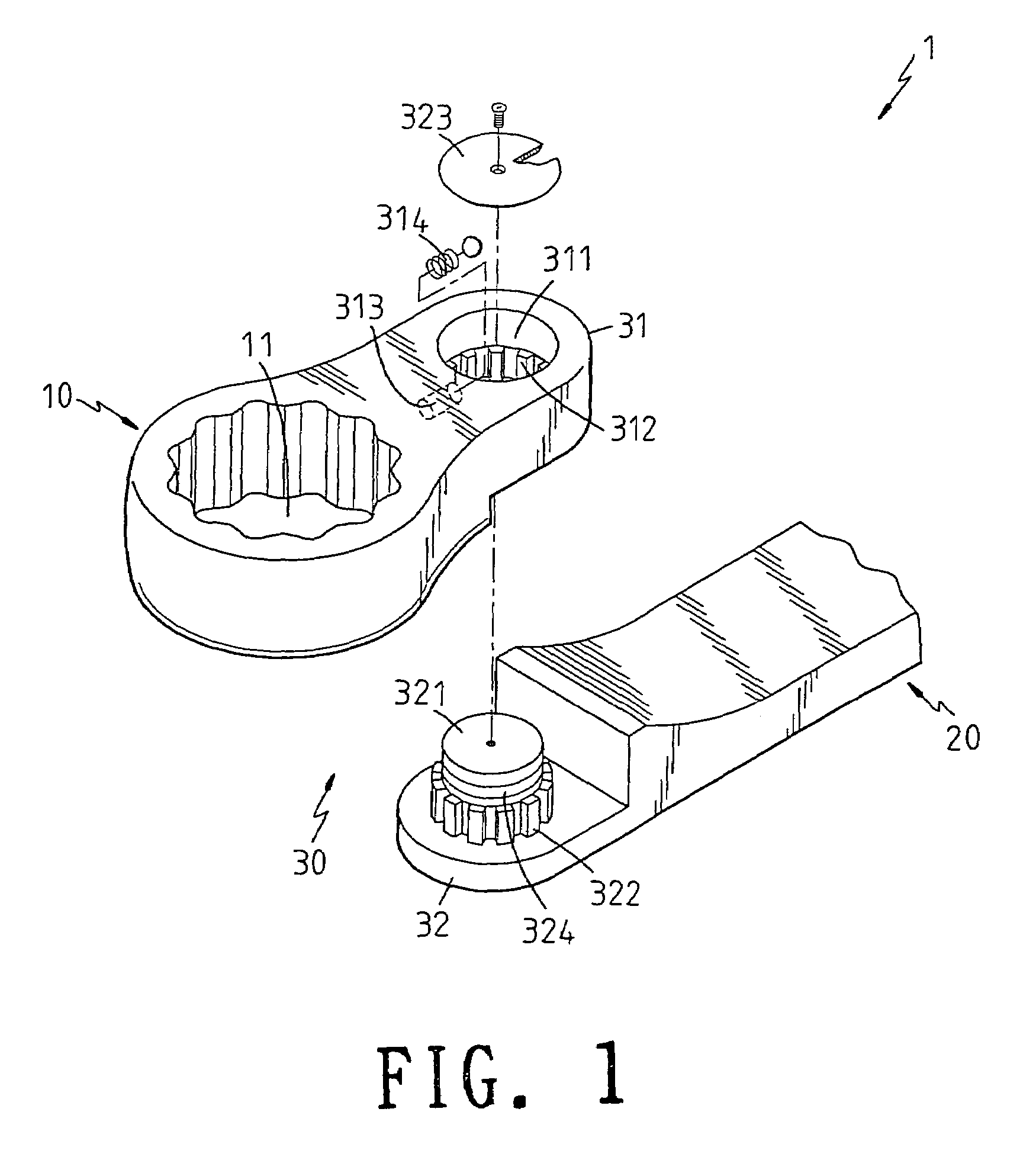
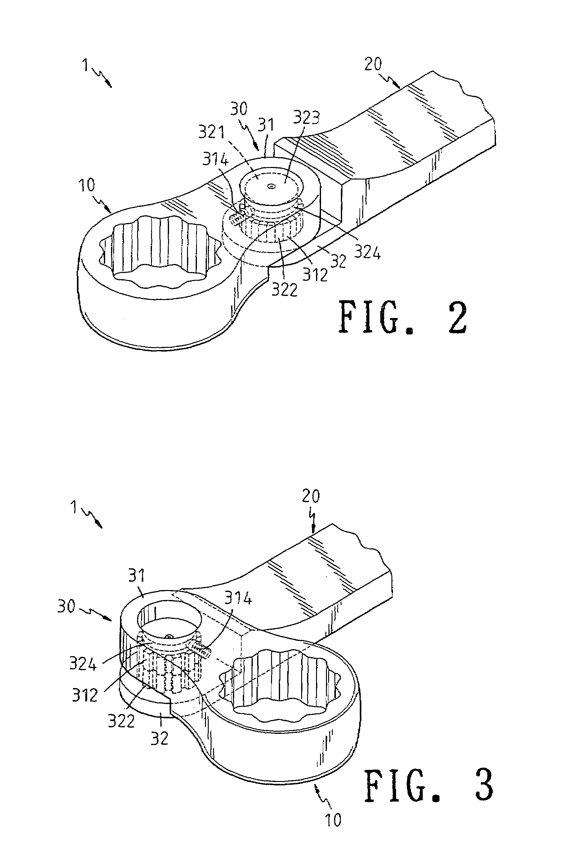
[0023]With reference to FIGS. 1 to 4, the structure of the present invention is illustrated. The present invention has a tool body 1. The tool body 1 has the following elements.

[0024]A driving portion 10 has a front end which is formed with a driving opening 11 for engaging with a screw element. The form of the driving opening 11 can have various forms, such as those illustrated in FIGS. 9, 10 and 11. Those the driving portion 10 illustrated in the drawing is not used to confine the scope of the present invention.

[0025]A handle 20 is as a force ap...


PUM


Abstract

A pivoting assembly of a hand tool comprising a tool body, the tool body including a driving portion, a handle and a pivotal portion; the pivotal portion having a first pivoted end and a second pivoted end; the first pivoted end being installed to one of the handle and driving portion; and the second pivoted end being installed to the other one of the handle and driving portion so that an angle between the handle and driving portion is adjustable. The first pivoted end is formed with a buckling hole; a tooth portion is formed in the buckling hole; the second pivoted end is formed with a post; the post is axially moveable with respect to the tooth portion of the buckling hole; and a bottom of the post is formed with teeth with respect to the tooth portion of the buckling hole.

Description

FIELD OF THE INVENTION[0001]The present invention relates to hand tools, and in particular to a pivoting assembly of a hand tool by which a driving portion of a hand tool is pivotally rotated with respect to the handle of the hand tool.BACKGROUND OF THE INVENTION[0002]In the prior hand tools, such as spanners, the tool generally has driving portion and a handle. The driving portion is engaged to a screw means for driving the screw means to rotate repeatedly. However the driving portion is retained to the handle, that is, the driving portion cannot rotate with respect to the handle so that if the work environment is not suitable for locating the spanner. The operator will feel uneasy in operation and the operation is inefficiency.[0003]There are some portions which aim at to an adjustable spanner for improving above mentioned defects, such as U.S. Pat. Nos. 5,419,221, 6,928,904 and Taiwan Patent No. 542053. In these prior arts, a pivotal portion is installed between a driving portion...

Claims


Application Information

Patent Timeline
Patent Type & Authority Patents(United States)
IPC IPC(8): B25B23/16
CPCB25G1/063Y10T403/32336Y10T403/32368
Inventor HSIEH, CHIH-CHING
Owner HSIEH CHIH CHING
Why Eureka
Try Eureka