Shielding component, in particular a heat shield

Inactive Publication Date: 2008-05-20
ELRINGKLINGER AG
View PDF13 Cites 2 Cited by
  • Summary
  • Abstract
  • Description
  • Claims
  • Application Information

AI Technical Summary

Benefits of technology

[0005]An object of the present invention is to provide an improved heat shield having very good aco

Problems solved by technology

While heat development, for example of a high-economy, performance-optimized diesel engine, can be very low on the cylinder crankshaft housing, this low heat development in no way applies to “hot zones” such as manifolds, turbochargers, catalytic converters, etc.
In this way, especially in thermal expansion processes for the shielding component, problems arise in fixing it, especially when, as in the indicated known solution, the shielding component is fixed within the engi

Method used


Image

  • Shielding component, in particular a heat shield
  • Shielding component, in particular a heat shield
  • Shielding component, in particular a heat shield

Examples


Embodiment Construction

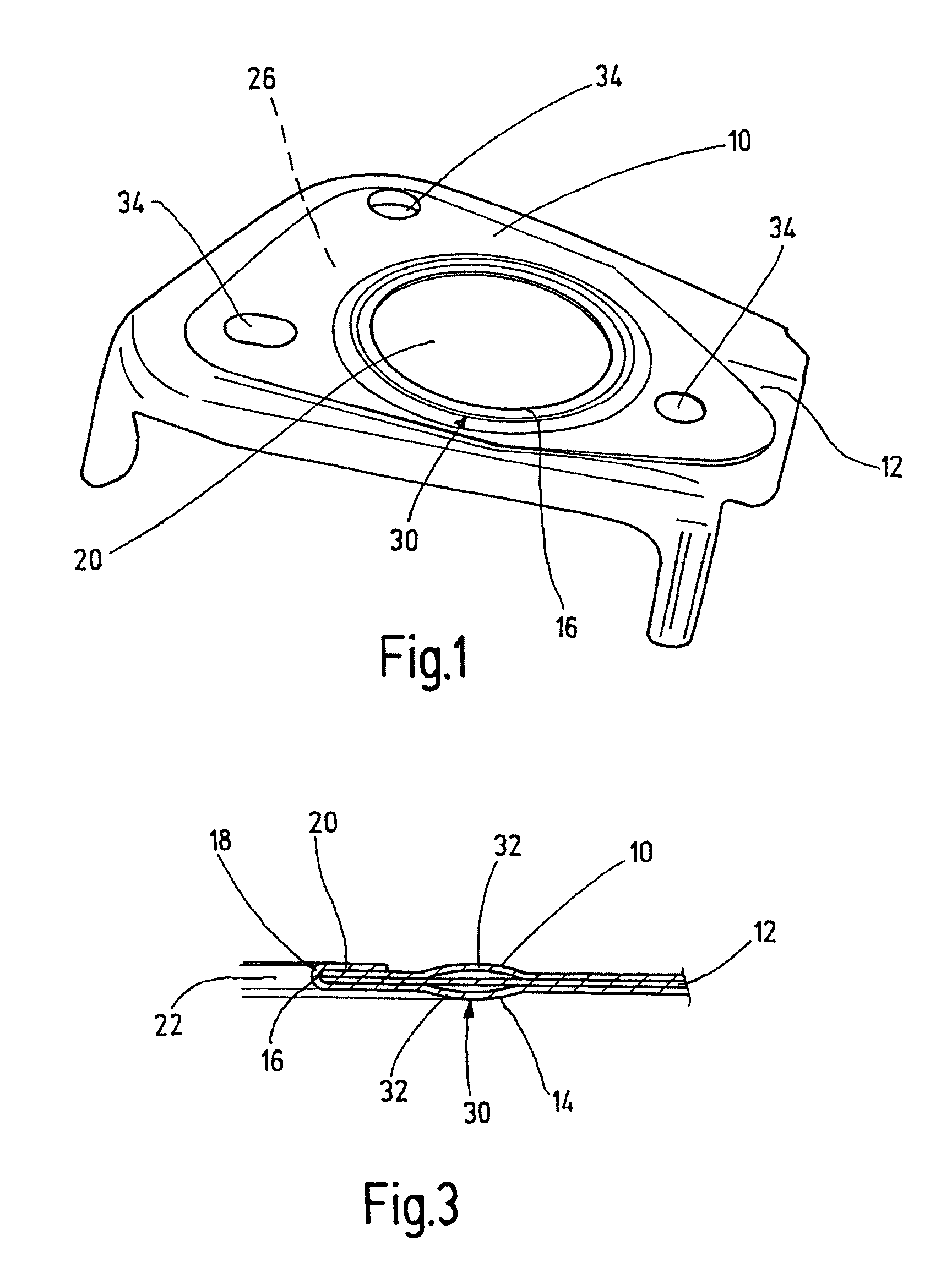
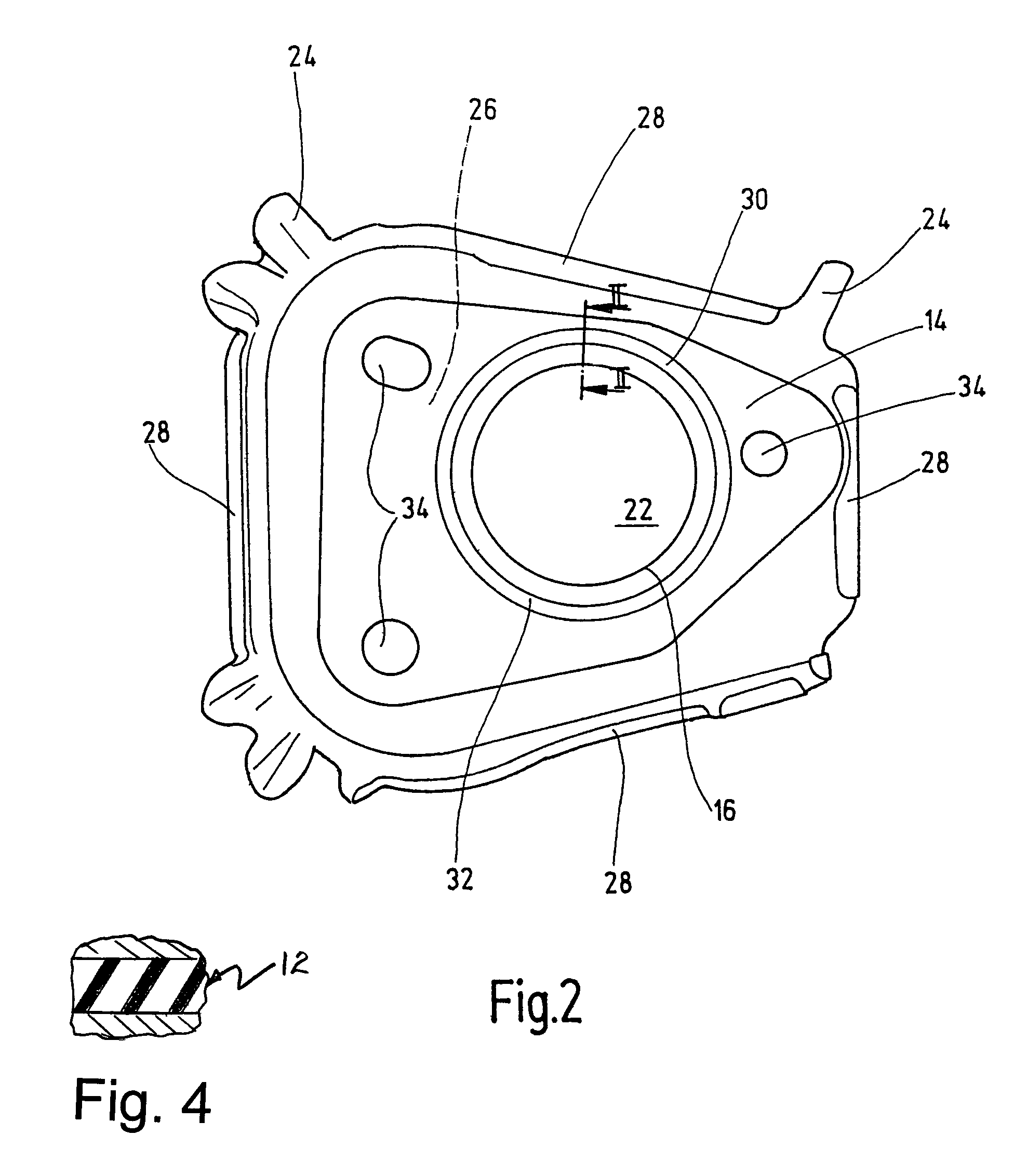
[0016]A shielding component according to the present invention is made, in particular, as a heat shield and has, at least in the middle area, individual shield components 10, 12, 14 lying partially flat on top of one another. These shield components 10, 12, 14 are connected to one another along a common connecting line 16. Along this common connecting line 16, the bottom shield component 14 shown in FIG. 2 encompasses the middle shield component 12 and the top shield component 10 on the edge side in an overlap 18 (compare FIG. 3). The overlap 18 is produced, in particular, by the bottom shield component 14 along an interior circumferential side end or edge being turned down with its free edge around a definable edge mounting 20. This edge mounting 20 determines essentially a defined compensation distance by which the shield components 10, 12, 14 are movably held by frictional engagement against one another to compensate for thermally occurring expansions, at least in the area of the...


PUM


Abstract

A shielding component, in particular a heat shield, has shield components (10, 12, 14) which are made flat, which lie at least partially on top of one another, and which are connected to one another at least partially along at least one common connecting line (16). Along the common connecting line (16), at least one shield component (14) encompassing another shield component (10, 12) in an overlap (18). Within the overlap (18), the shield components (10, 12, 14) are held at least partially by frictional engagement so as to be displaceable against one another relative to a compensation distance. A rigid connection of the shield components with their individual layers is avoided. Rather, depending on the thermal situation, they can mutually slide off one another.

Description

REFERENCE TO RELATED APPLICATION[0001]This application is related to U.S. patent application Ser. No. 11 / 133,453, entitled “Shielding Component, in Particular a Heat Shield” filed on May 20, 2006 in the names of Ulrich Beutter and Harald Stauber.FIELD OF THE INVENTION[0002]The present invention relates to a shielding component, in particular a heat shield, formed of shield components. The shield components are made flat, lie at least partially on top of one another, and are connected to one another at least partially along at least one common connecting line. Along the common connecting line, at least one shield component encompasses another shield component in an overlap.BACKGROUND OF THE INVENTION[0003]While heat development, for example of a high-economy, performance-optimized diesel engine, can be very low on the cylinder crankshaft housing, this low heat development in no way applies to “hot zones” such as manifolds, turbochargers, catalytic converters, etc. Due to the more and...

Claims


Application Information

Patent Timeline
IPC IPC(8): F02F11/00F16L21/02F01N13/14
CPCB60R13/0876F01N13/14F01N13/141F16L59/08
Inventor BEUTTER, ULRICHSTAUBER, HARALD
Owner ELRINGKLINGER AG
Why Eureka
Try Eureka