Fiber stub with optical element, optical receptacle and optical module

a fiber stub and optical element technology, applied in the field of fiber stubs with optical elements, optical receptacles and optical modules, can solve the problems of increasing the total size of the optical module, unable to regulate the position of the optical element, and the outer diameter of the magnet b>10/b> becoming large, so as to achieve simplified isolation

Active Publication Date: 2008-05-20
KYOCERA CORP
View PDF9 Cites 8 Cited by
  • Summary
  • Abstract
  • Description
  • Claims
  • Application Information

AI Technical Summary

Benefits of technology

[0017]Furthermore, it is necessary to provide in the inner portion of the lens holder 16 a counterbore portion 21 having a diameter larger than the outer diameter of the magnet 10, and deep enough for the magnet 10 not to make contact with the lens holder 16, even when the optical receptacle 17 is shifted to the front or rear at the time of optical axis adjustment. If the magnet 10 makes contact with the inside of the counterbore portion 21, the joint portion of the magnet 10 may separate. Therefore, it is necessary to create a sufficiently large counterbore portion 21, which results in increased dimensions of the lens holder 16. Thus, the size of the optical module becomes large.
[0039]When the insertion loss is measured, light may be made to enter into the optical isolator side of the fiber stub, and maximum output P1 of light that is emitted from the rear end of the fiber stub may be measured while the fiber stub with an optical isolator is being rotated around the optical axis, so that the insertion loss can be measured on the basis of this maximum output P1. When the isolation is measured, light may be made to enter from the rear end side of the fiber stub with an optical isolator, and maximum output P2 of light that is emitted from the optical isolator may be measured while the fiber stub with an optical isolator is being rotated around the optical axis, so that the isolation can be measured on the basis of this maximum output P2. By measuring the insertion loss and the isolation according to these methods, the use of a polarization scrambler for converting output light from a light source into random polarized waves can be eliminated. In addition, the insertion loss and the isolation can be measured only by inverting the direction of the fiber stub itself, instead of inverting the polarities of the magnet. Accordingly, the inspection unit and the inspection process for the insertion loss and the isolation can be simplified.

Problems solved by technology

In addition, no means is provided to regulate the position of the optical element 9.
This leads to an increase in the total size of the optical module.
The conventional optical module has such a structure that the magnet 10 in cylindrical form is secured to the fiber stub 3 through insertion, and thereby attached to an end surface of the metal holder 5, and therefore, a problem arises that the outer diameter of the magnet 10 becomes large.
In such a structure, however, a problem arises that the fixing strength of the magnet 10 is lowered, or the magnet 10 and the optical isolator element 9 go out of the alignment with each other.
Thus, the size of the optical module becomes large.

Method used


Image

  • Fiber stub with optical element, optical receptacle and optical module
  • Fiber stub with optical element, optical receptacle and optical module
  • Fiber stub with optical element, optical receptacle and optical module

Examples


examples

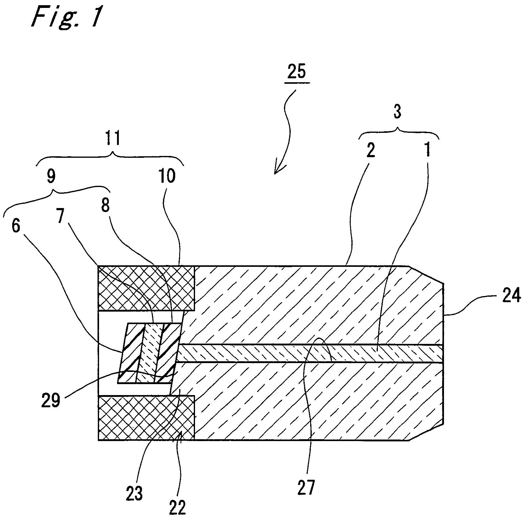
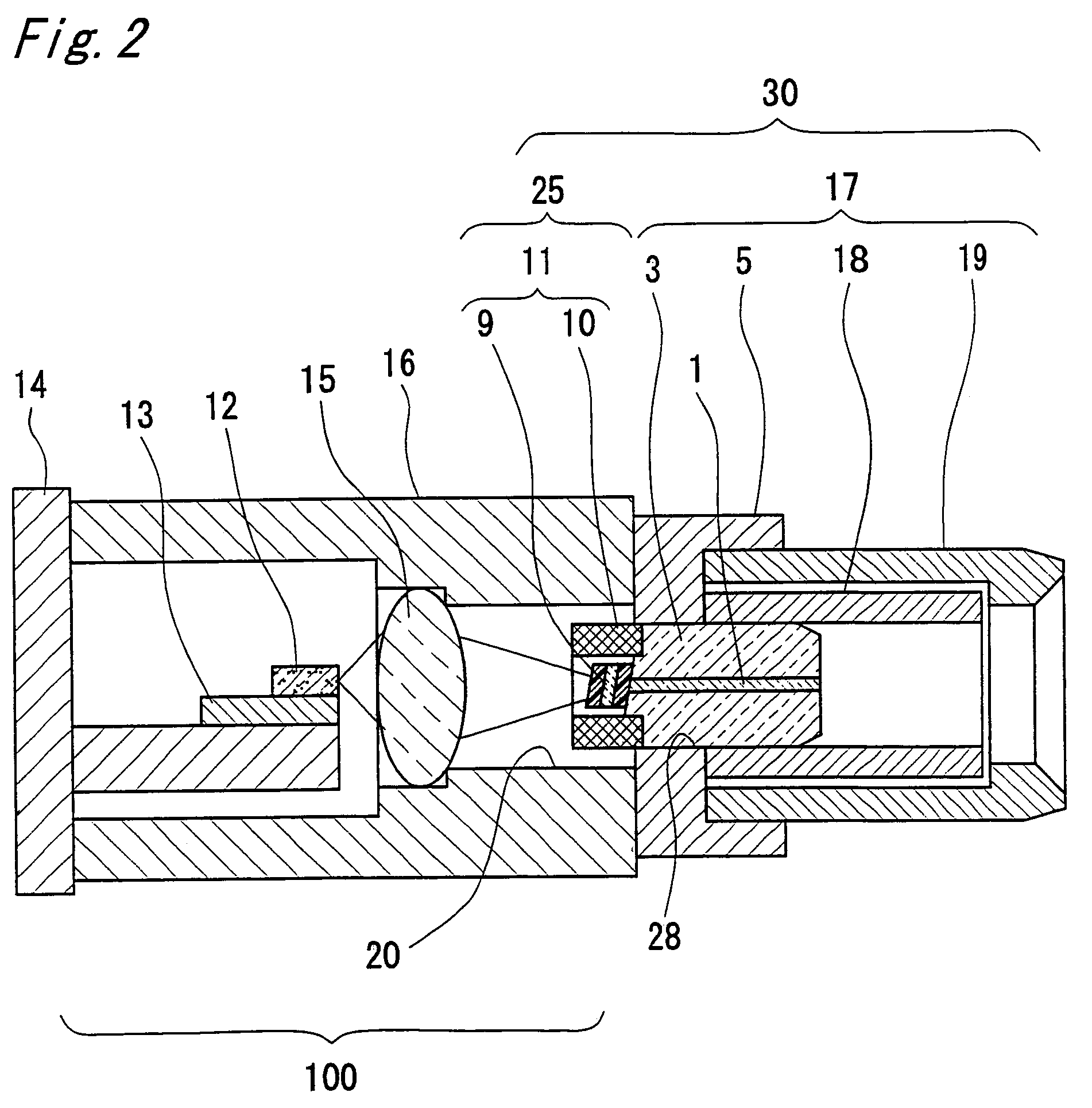
[0086]In the following, an optical module having a fiber stub with an optical isolator as shown in FIGS. 1 and 2, as well as an optical receptacle, was fabricated as an example of the present invention. The optical module was a coaxial optical receptacle type semiconductor laser module.

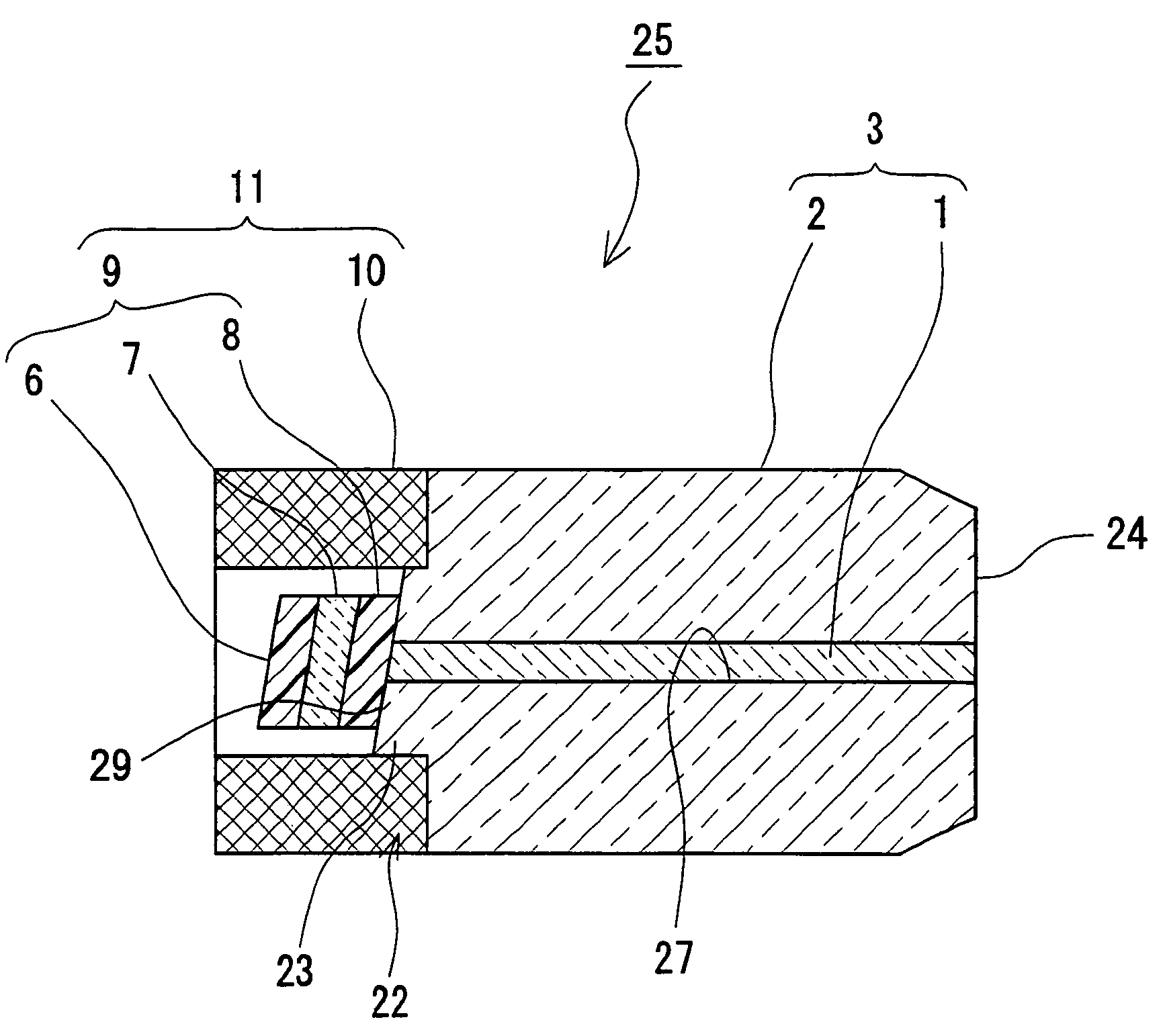
[0087]As shown in FIG. 1, d fiber stab 3 was formed by securing the optical fiber 1 by means of adhesion to the through hole 27, of which outer diameter was 1.25 mm, located at the center of the ferrule 2 made of zirconia. A step 22 was formed by processing the front end side of the fiber stub 3, and thus, a protrusion 23 having an outer diameter of 0.5 mm was provided. Then, the surface 29 of the protrusion 23 was polished to incline by 8°. In addition, the rear end surface of the fiber stub 3 was polished to have a curved surface so that it could be engaged with the end of a plug ferrule of an optical connector, which is not shown.

[0088]Meanwhile, as shown in FIG. 3, the surface of the optical isola...


PUM


Abstract

In a semiconductor laser module with an optical isolator where the form of a metal holder for holding a fiber stub varies, optical-isolator parts are miniaturized and unified, simplifying product management, reducing delivery time and cost. A fiber stub with an optical isolator is provided in such a manner that a stepped surface is formed on an end surface of a ferrule, where an optical fiber has been inserted and secured to a through hole formed at the center of the ferrule. The fiber stub is formed by attaching an optical isolator element composed of a polarizer and a Faraday rotator to the stepped surface.

Description

BACKGROUND OF THE INVENTION[0001]1. Field of the Invention[0002]The present invention relates to a fiber stub in which an optical element such as an optical isolator is mounted, an optical receptacle and an optical module.[0003]2. Description of the Related Art[0004]An optical element such as an optical isolator for preventing reflected light from returning is generally incorporated into compact semiconductor laser modules which are mounted with high density in an optical transceiver that is utilized for optical communication. For example, Patent Document 1 and Patent Document 2 disclose a conventional fiber stub with an optical isolator, as well as an optical receptacle and an optical module which use such a fiber stub. The internal structures of these are described in reference to FIGS. 8 and 9. FIG. 8 is a longitudinal cross-sectional diagram of the main portion of a conventional fiber stub with an optical isolator. FIG. 9 is a longitudinal cross-sectional diagram of an optical m...

Claims


Application Information

Patent Timeline
Patent Type & Authority Patents(United States)
IPC IPC(8): G02B6/26G02B6/42G02B6/36
CPCG02B6/4209G02B6/421G02B6/4292
Inventor TANAKA, TSUYOSHIHIROSE, TOMOYUKINAKASHIMA, KAICHIROSHODA, MICHIFUMI
Owner KYOCERA CORP
Why Eureka
Try Eureka