Connecting device of a flexible printed circuit board

a flexible printed circuit board and connecting device technology, applied in the direction of coupling contact members, coupling device connections, laminating printed circuit boards, etc., can solve the problems of difficult compactness of the apparatus, high difficulty in insertion of fpc boards into insertion slots, and high difficulty in ensuring the safety of the device, so as to facilitate the connection to the connector and increase workability

Inactive Publication Date: 2008-05-20
JAPAN DISPLAY WEST
View PDF24 Cites 7 Cited by
  • Summary
  • Abstract
  • Description
  • Claims
  • Application Information

AI Technical Summary

Benefits of technology

[0028]In view of the conventionally experienced inconveniences and disadvantages discussed above, it is an object of the present invention to provide a connecting device of a flexible printed circuit board that has a reinforced backlight FPC board, that is free from bad contact resulting from insufficient insertion of a terminal portion of a flexible printed circuit board into a connector, and that ensures good connection without leaving contaminants, scratches, or the like on contacts of the terminal portion.
[0030]By bonding a reinforcing plate in a terminal portion of a flexible printed circuit board and forming an ear-like piece in the reinforcing plate as described above, it is possible, when the flexible printed circuit board is connected to a connector, to confirm how deep it has been inserted into an insertion slot of the connector, that is, to confirm, based on insertion depth, whether or not a contact of the terminal portion and a contact of the connector have been properly connected together. Thus, it is possible to prevent bad connection resulting from insufficient insertion.
[0032]By bonding a reinforcing plate in a terminal portion of a flexible printed circuit board, forming an ear-like piece in the reinforcing plate as described above, and making the reinforcing plate dagger-shaped as described above, it is possible to make connection to a connector easy and increase workability.

Problems solved by technology

This makes it difficult to make the apparatus compact, and makes interference with an obstacle likely.
Thus, the FPC board is extremely difficult to insert into an insertion slot, and requires skilled work for its connection to a connector.
Even when this is practiced, insertion is still considerably difficult.
This makes insertion into an insertion slot more difficult.
Moreover, even when the terminal portion is inserted into the insertion slot, since the shape of the terminal portion is indefinite as described above, it is difficult to confirm whether the terminal portion has been inserted up to the right position, and, if not, bad contact may result.
Such insufficient insertion may go undetected through electrical conduction inspection performed after assembly, causing disconnection resulting from vibration or the like during use, and thus leading to failure of an appliance.
During this work, the fingers or tool may make contact with the contacts of the terminal portion, leaving contaminants, scratches, or the like on the surface of the contacts, and thus leading to bad contact.

Method used


Image

  • Connecting device of a flexible printed circuit board
  • Connecting device of a flexible printed circuit board
  • Connecting device of a flexible printed circuit board

Examples


first embodiment

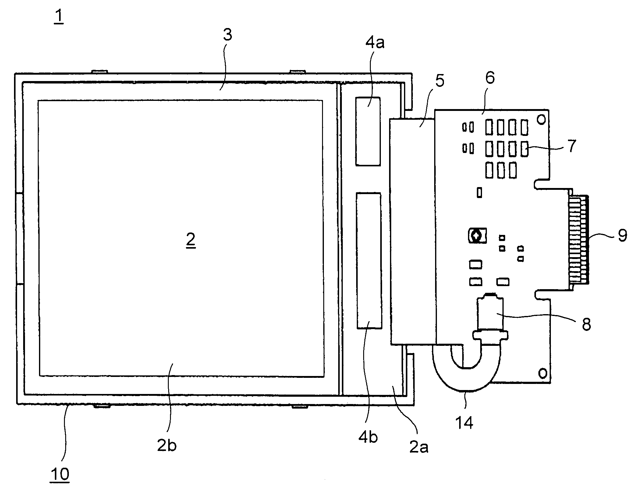
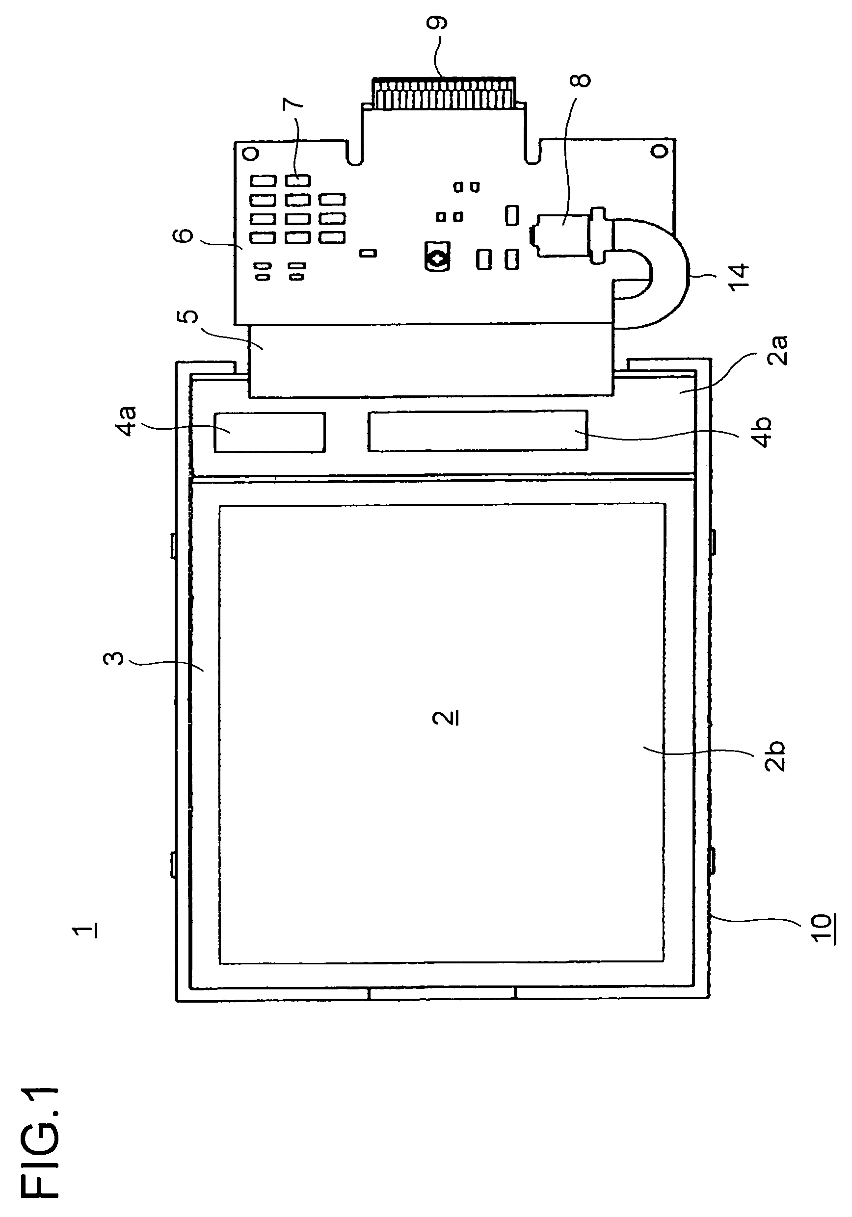
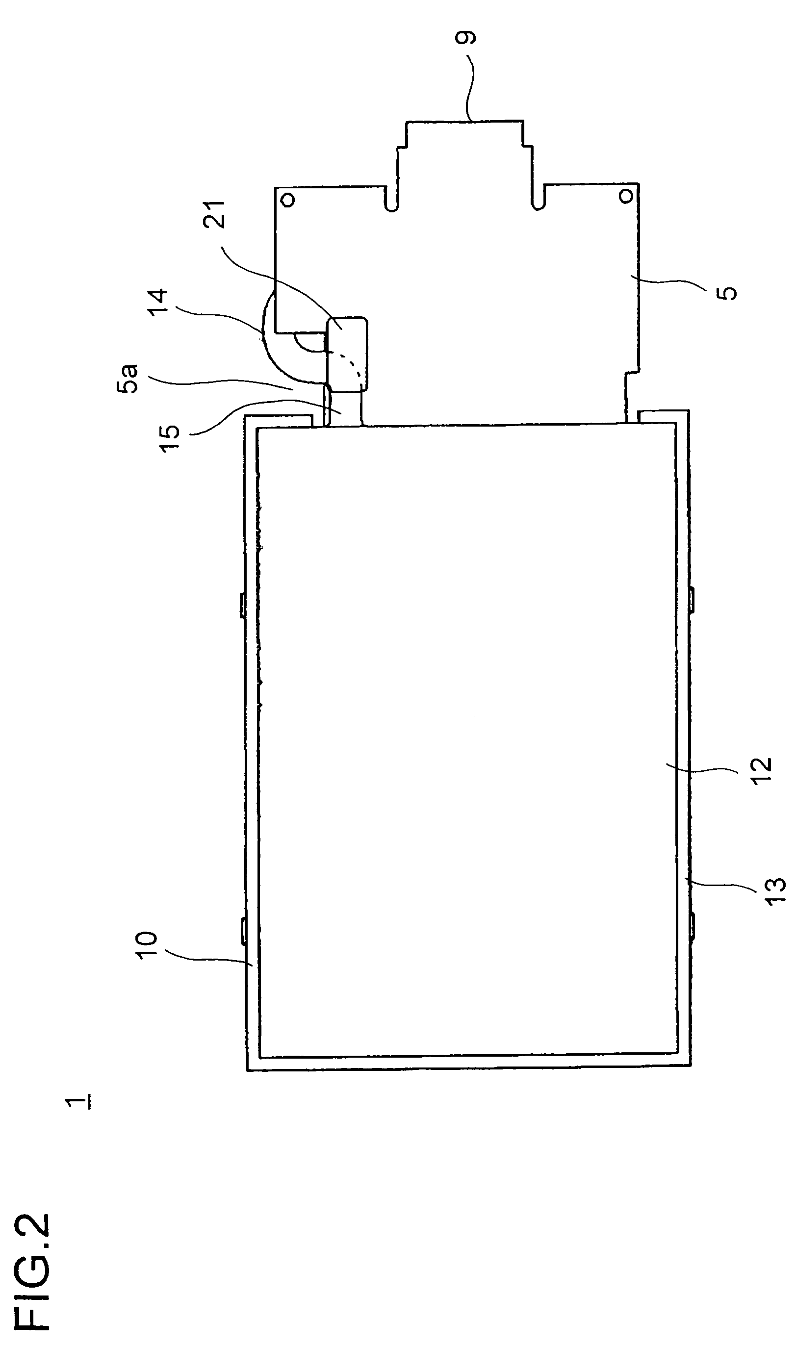
[0044]FIG. 1 is a front view of a connecting device in an FPC board of a first embodiment of the invention, as applied to a liquid crystal display apparatus. FIG. 2 is a rear view of the liquid crystal display apparatus shown in FIG. 1. FIG. 3 is a front view of a backlight unit. FIG. 4A is a front view of the backlight FPC board used in the backlight unit shown in FIG. 3, FIG. 4B is a sectional view along line A—A shown in FIG. 4A, and FIG. 4C is a perspective view showing a state in which a terminal portion of the backlight FPC board is inserted into a connector. FIG. 5A is a side view of FIG. 1, and FIG. 5B is an enlarged view of part B shown in FIG. 5A.

[0045]As shown in FIGS. 1 and 2, the liquid crystal display apparatus 1 is provided with a liquid crystal display panel 2 and a backlight unit 10 for illuminating the liquid crystal display panel 2. The liquid crystal display panel 2 is provided with an array substrate 2a having thin-film transistors and transparent pixel electrod...


PUM


Abstract

A connecting device of a flexible printed circuit board has a reinforced backlight FPC board, is free from bad contact resulting from insufficient insertion of a terminal portion of a flexible printed circuit board into a connector, and ensures good connection without leaving contaminants, scratches, or the like on contacts of the terminal portion. The connecting device of a flexible printed circuit board has a terminal portion having a contact formed as a printed conductor in a tip end portion of a film-form flexible printed circuit board, and a connector having an insertion slot into which the terminal portion is inserted and a contact fitted inside the insertion slot and connected to the contact of the terminal portion. Moreover, a reinforcing plate is bonded on the face of the terminal portion opposite to the face thereof on which the contact is formed, and an ear-like piece that makes contact with the opening rim of the insertion slot in the connector is formed in a position a predetermined distance inward from the tip end of the terminal portion in the length direction of the flexible printed circuit board.

Description

[0001]The present application claims the benefit of patent application No. 2005-8667, filed in Japan on Jan. 17, 2005, the subject matter of which is hereby incorporated herein by reference.BACKGROUND OF THE INVENTION[0002]1. Field of the Invention[0003]The present invention relates to a connecting device of a flexible printed circuit board. More particularly, the present invention relates to a connecting device in which a terminal portion of a flexible printed circuit board to be connected to a connector has an improved terminal portion, and especially to one suitable for use in a liquid crystal display apparatus.[0004]2. Description of Related Art[0005]Liquid crystal display apparatuses are widely used as displays in various electronic appliances such as cellular phones, video cameras, notebook personal computers, electronic dictionaries, and television monitors.[0006]A liquid crystal display apparatus is composed of a liquid crystal display panel having liquid crystal sealed ther...

Claims


Application Information

Patent Timeline
Patent Type & Authority Patents(United States)
IPC IPC(8): H01R12/00H01R13/02H05K1/11
CPCH01R13/025H05K1/118H01R12/79H01R12/721H01R12/774H05K3/0058H05K2201/09145H05K2201/2009H05K2203/167H01R12/775H01R12/77H01R13/58
Inventor IDENISHI, NAOHIRO
Owner JAPAN DISPLAY WEST
Why Eureka
Try Eureka